
Home
Shop
Tools
Empennage
Wings
Wings 2
Fuselage
Fuselage 2
Fuselage 3
Fuselage 4
Baggage Compartment
Aft Seat Floors
Forward Seat Floors
Elevator Servo Bracket
Seat Backs
Forward Covers
Installing the Flaps
Landing Gear Mounts
Installing Cabin Systems
Installing Aileron Boots
Elev Servo Speed Control
Fuselage 5
Fuselage 6
Panel
Firewall Forward
Canopy
Wiring
Miscellaneous
Fuselage 4
|
Date |
Description of Task | Hours |
| Baggage
Compartment |
||
| 8/28/07 | Deburred and clecoed the rear baggage bulkhead.
Trimmed and deburred the forward baggage side covers.
Deburred and temp installed the baggage tunnel cover. |
2.0 |
| 8/31/07 | Disassembled the baggage floor and sides and
scuffed. Scuffed the baggage side skins. Deburred
the cabin seat skins. |
2.0 |
| 9/1/07 | I chemically treated the aft baggage side skins
as well as the baggage floor sections and baggage tunnel cover
using SanChem. Next, I riveted the aft baggage covers.
I also blind riveted the baggage floors and riveted the
platenuts for the center tunnel cover. |
3.0 |
| 9/2/07 | Today dimpled and riveted the platenuts for the
aft baggage floor and the F-706 bulkhead. I worked on the
F-751 and F-652 corrugated baggage bulkheads. I trimmed
the F-652 to the correct radius and deburred.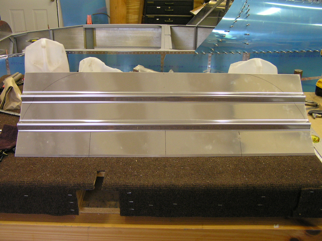
I drilled and trimmed the slot for the shoulder harness cables.
Finally, I marked a line on the F-751 lower bulkhead where the
F-652 upper bulkhead will fit. I match-drilled and clecoed
the lower bulkhead using the pre-drilled holes as a guide.
Holding the F-652 upper bulkhead to the line, I drilled and
clecoed it in place. I test fit the F-749 forward baggage side covers and clecoed
in place. |
3.0 |
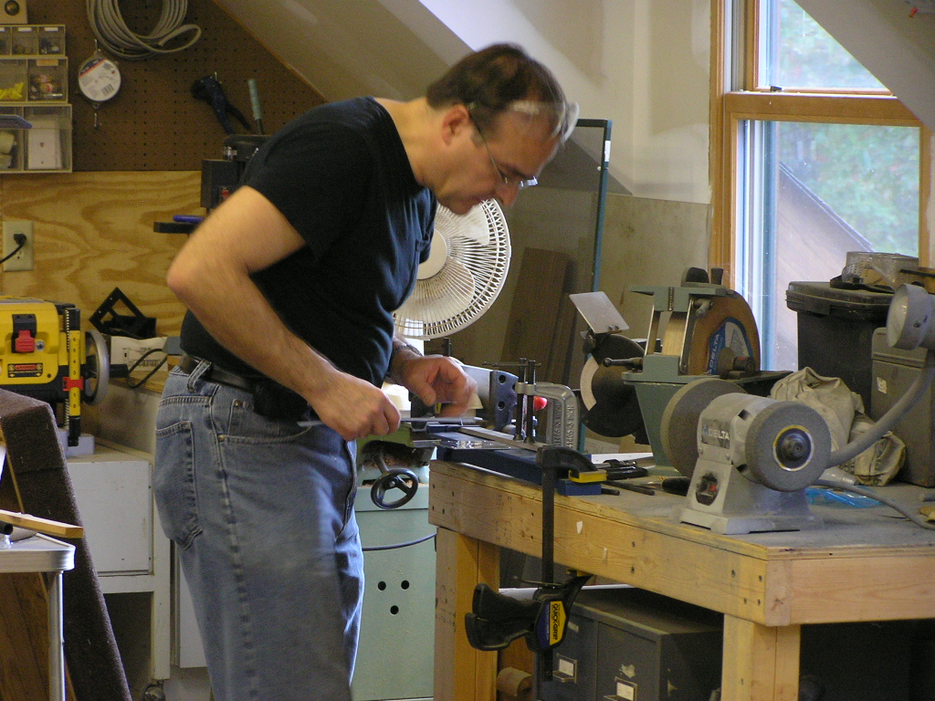
| 9/3/07 | Today I celebrated Labor Day by deburring the
baggage bulkheads and riveting the many platenuts to the F-706
bulkhead. It is times like this during the construction
process that I am really glad I bought a particular tool.
The tool is the #8 Platenut Jig I got from
Avery Tools. With all the platenuts I have to install,
it makes a tedious task much quicker and more bearable and every
platenut is perfectly aligned. Well worth the cost in my
opinion.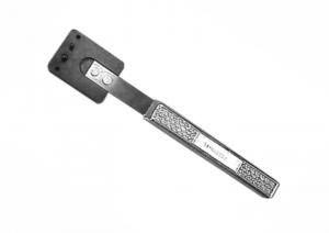 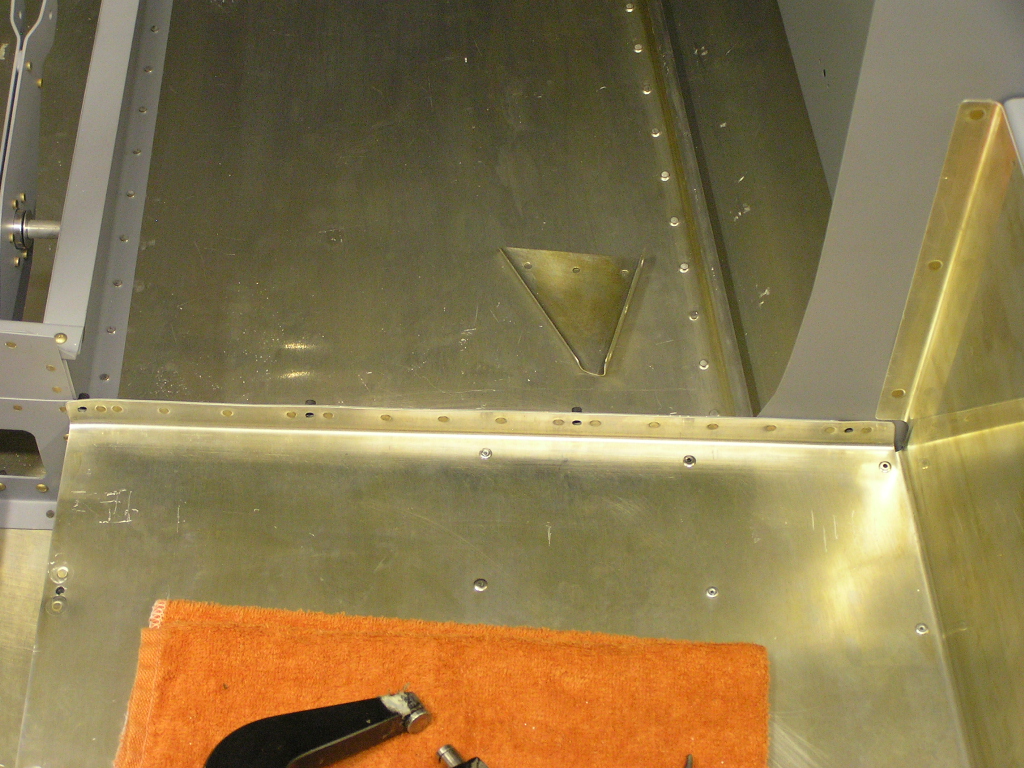
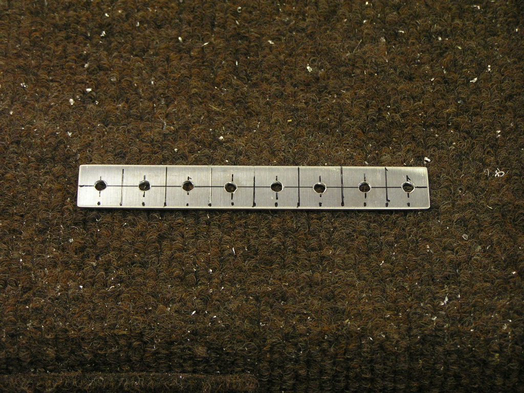
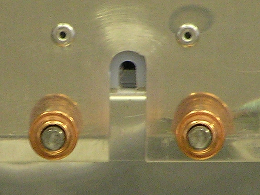
The next step is to install the guide blocks for the shoulder
harness cables. I marked out the AL strip for the eight
washers and cut with my snips. I then drilled the baggage
bulkheads and installed the guide blocks with LP4-3 blind
rivets. I then removed the aft fuselage top skins and riveted the
F-707 to the support angle. I also riveted the platenuts
to the F-749 forward baggage side covers and temporarily
installed. I also drilled, deburred and riveted the aft F-656 bulkhead
braces. I also test painted the upper support ribs to get
a feel for the hammered gray color... We'll see. |
5.0 |
|
Aft Seat Floors |
||
Next, I moved on to the seat adjustment hinges.
The plans simply say "Install the hinges" so I had to study the
drawings and figure out what to do. I cut six hinges 15
1/2" and deburred and marked for drilling to the seat pans.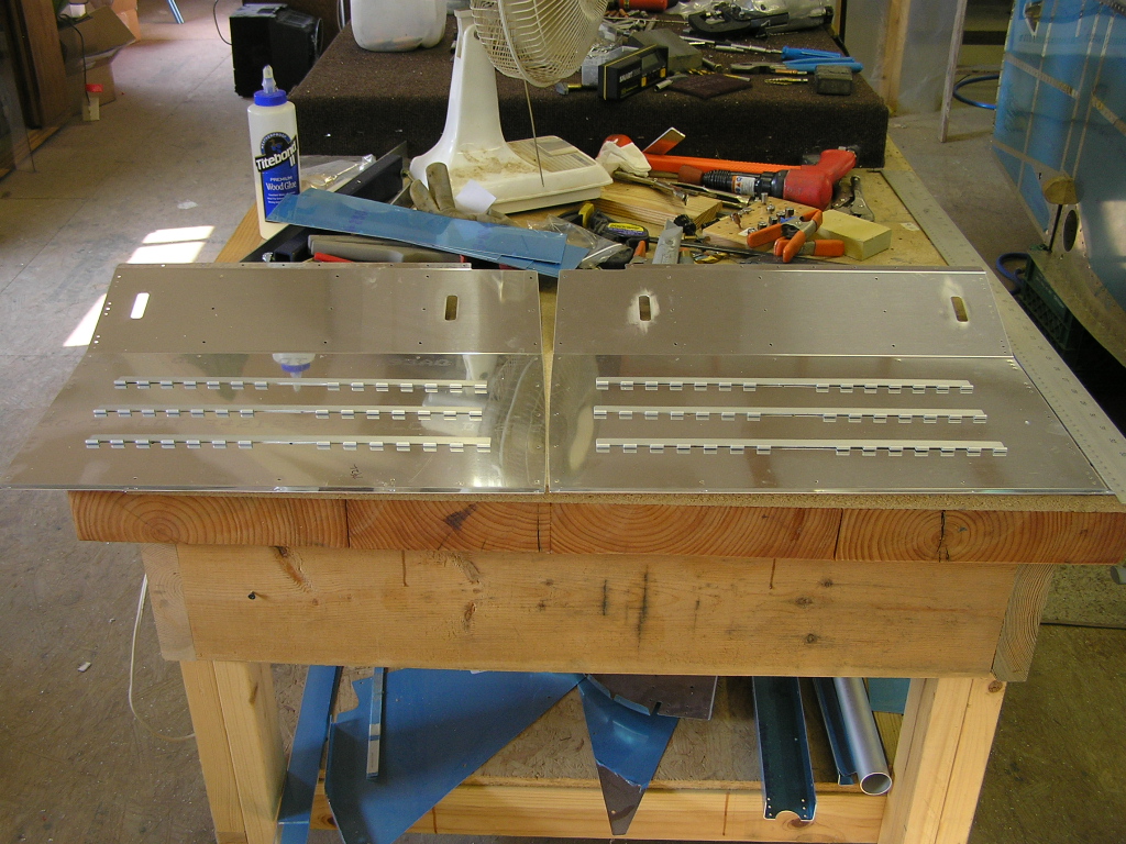 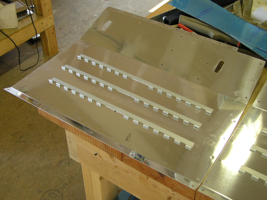 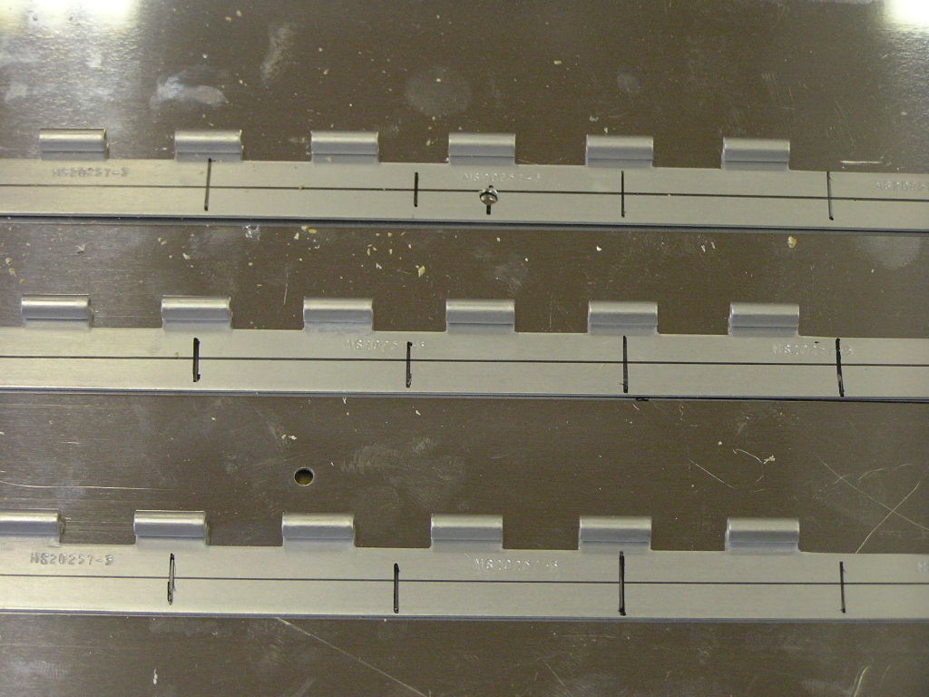 |
||
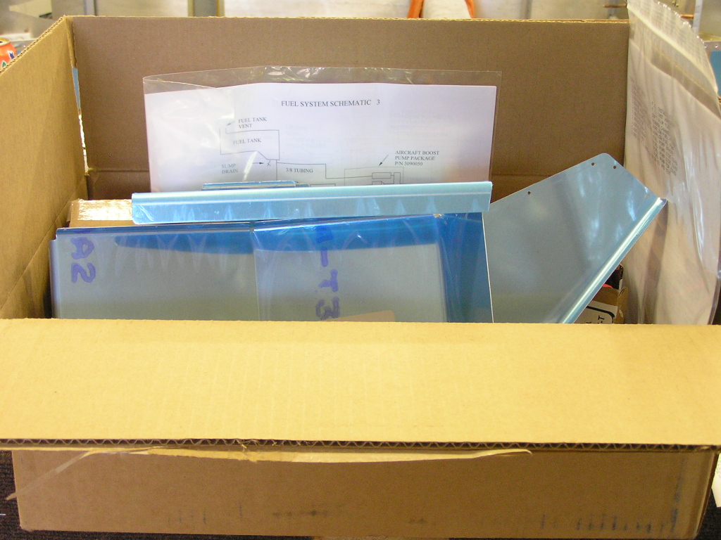
| 9/5/07 | This was a big week for parts orders. I
received my COM1 antenna from
SteinAir, a Comant CI122 bent whip that will go
on the belly near the left main gear leg. I also received
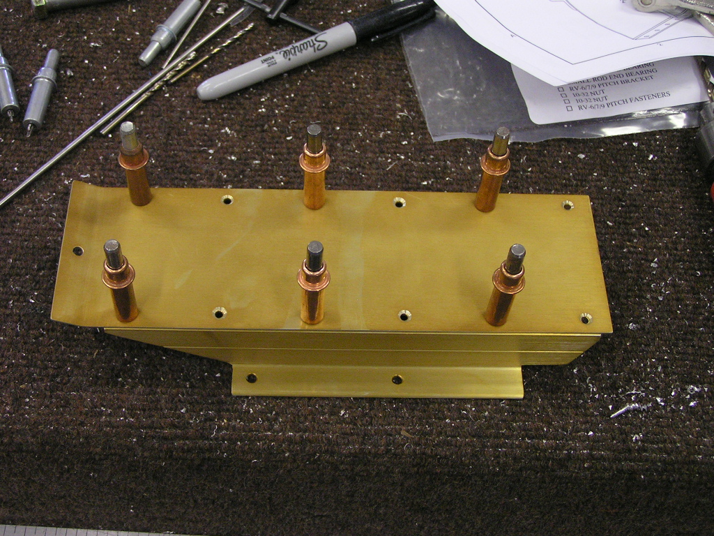
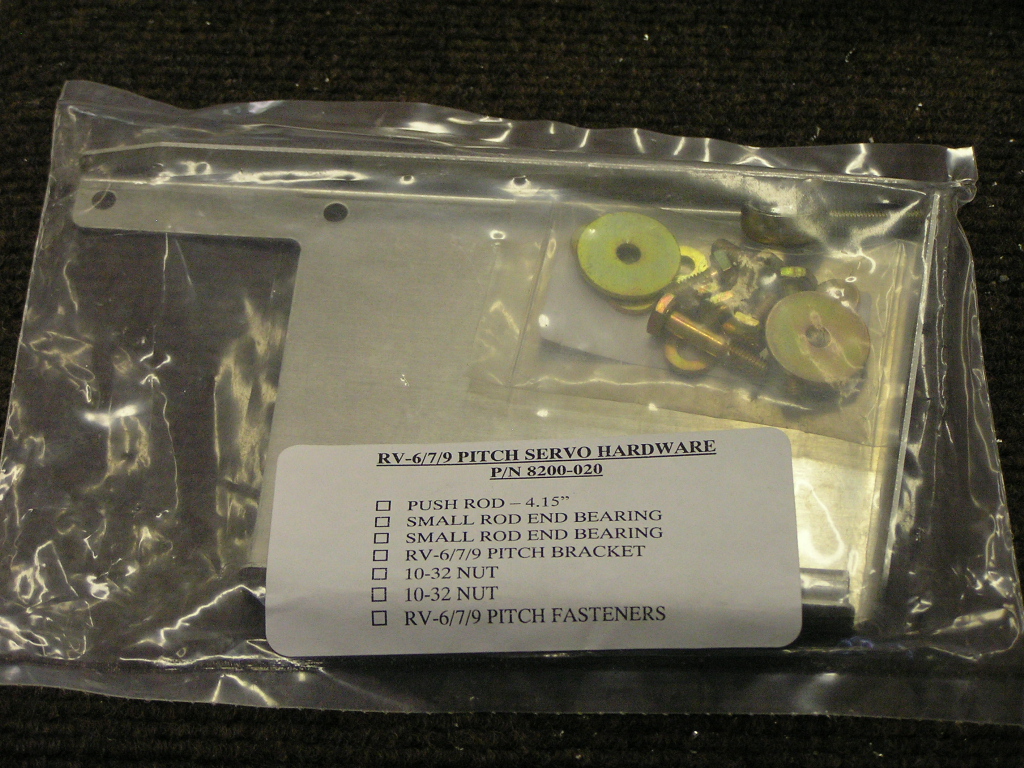
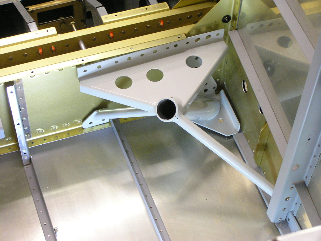
my transponder antenna. I have already installed my servo bracket for the TruTrak AP in the
wing but needed the bracket for the elevator servo. Stein
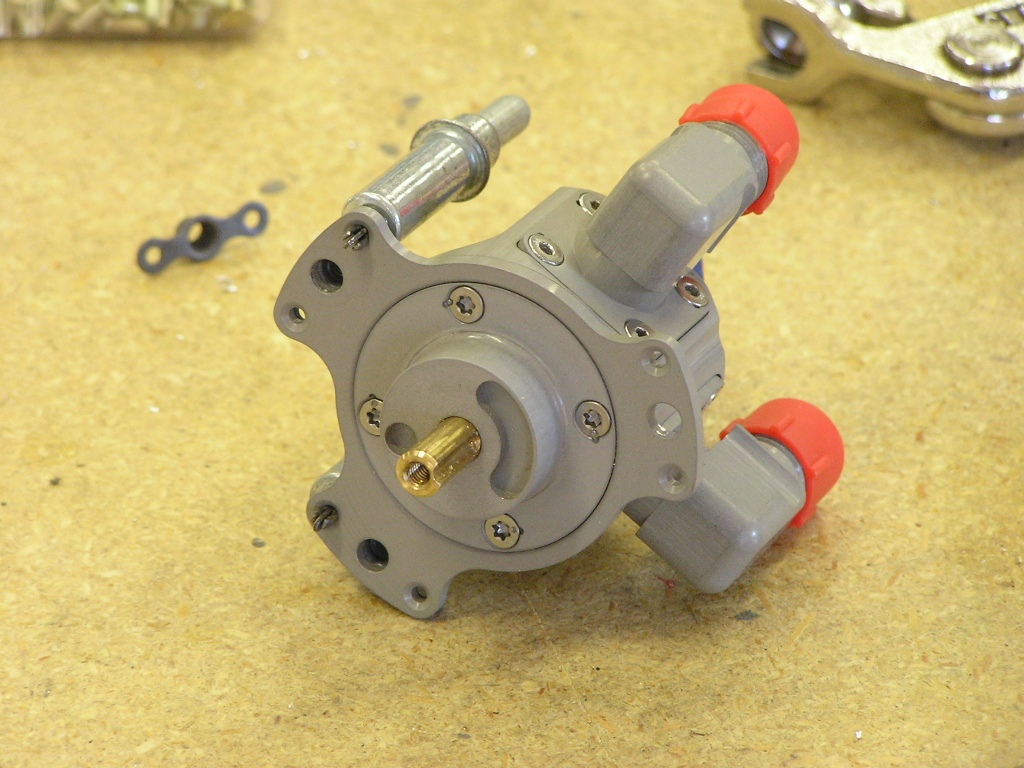
fixed me up. I also received my Airflow Performance fuel injection pump assembly as
well as an Andair fuel valve. I was able to drill the hinges for rivets using the drill
press. |
1.0 |
| 9/7/07 | Continued work on the aft seat floors by
drilling the hinges to the seats to #30 and deburred. I
then clecoed the aft seat floors to the cabin ribs. |
3.5 |
|
Forward Seat Floors |
||
| I clecoed the F-939 and F-940 Forward Seat
Floors to the seat ribs. I fabricated the F-741A-L&R
Tunnel Support Covers using the bandsaw and drilled the lower
flanges to the aft seat floors. I then fabricated the
F-741B Tunnel Cover and drilled to the tunnel support covers and
the forward seat floor. I then took it all apart and
deburred. |
||
| 9/8/07 | I spent most of the day chemically treating
(SanChem) the aft and forward seat floors. 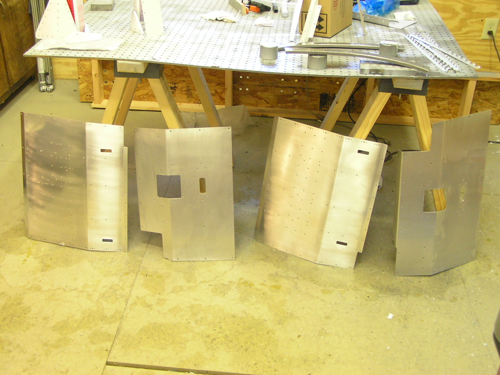
I also alodined a lot of additional bits and pieces while I was
at it. I also installed platenuts on the outboard seat
ribs, installed the aft bulkhead-to-longeron brackets, installed
the shoulder harness brackets and riveted the F-741B tunnel
cover to the support brackets. I clecoed the aft seat floors and seat hinges and used LP4-3
blind rivets to install. I also cut to length and bent the
hinge pins that will attach the seat backs to the floor.
All went well other than my back is really sore from bending
over the fuselage to install the 100+ rivets.
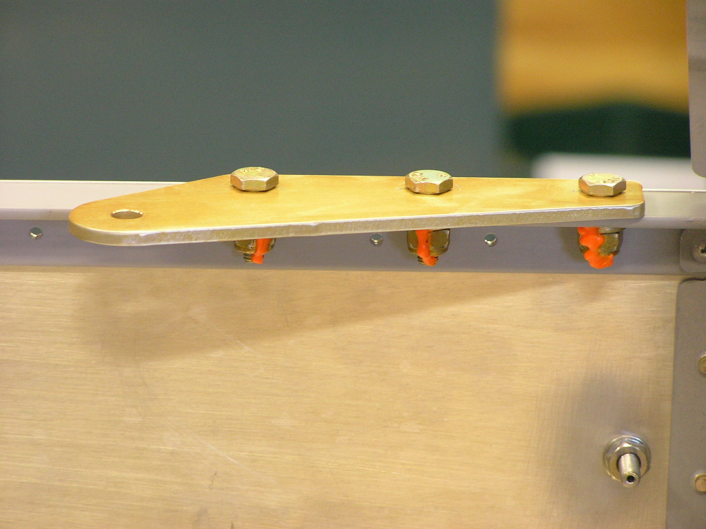
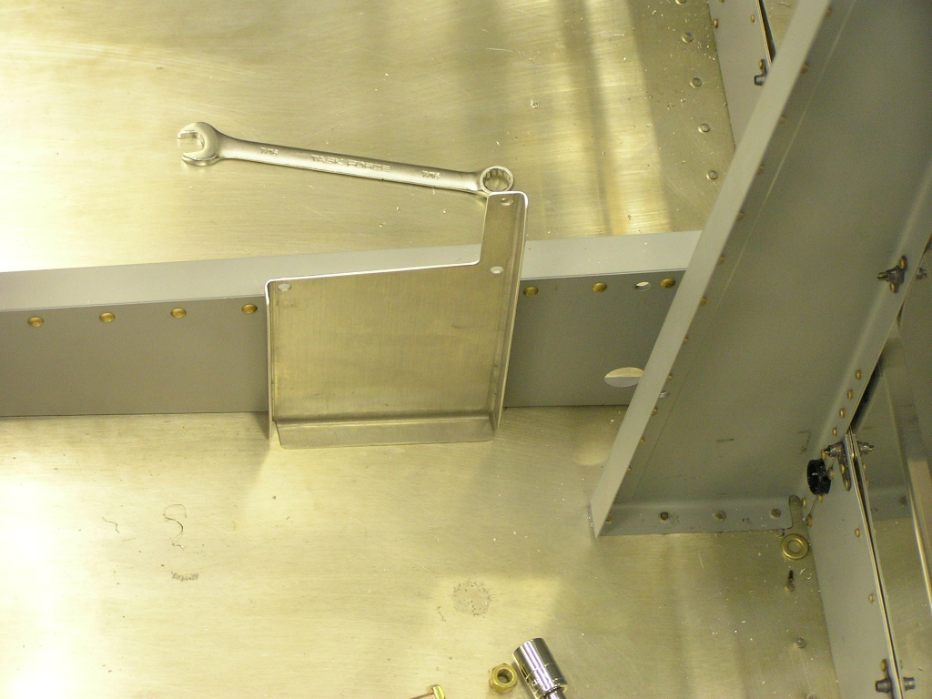
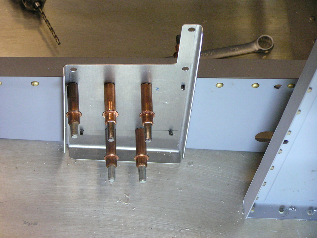
TruTrak Autopilot Elevator
Servo Bracket Install |
6.5 |
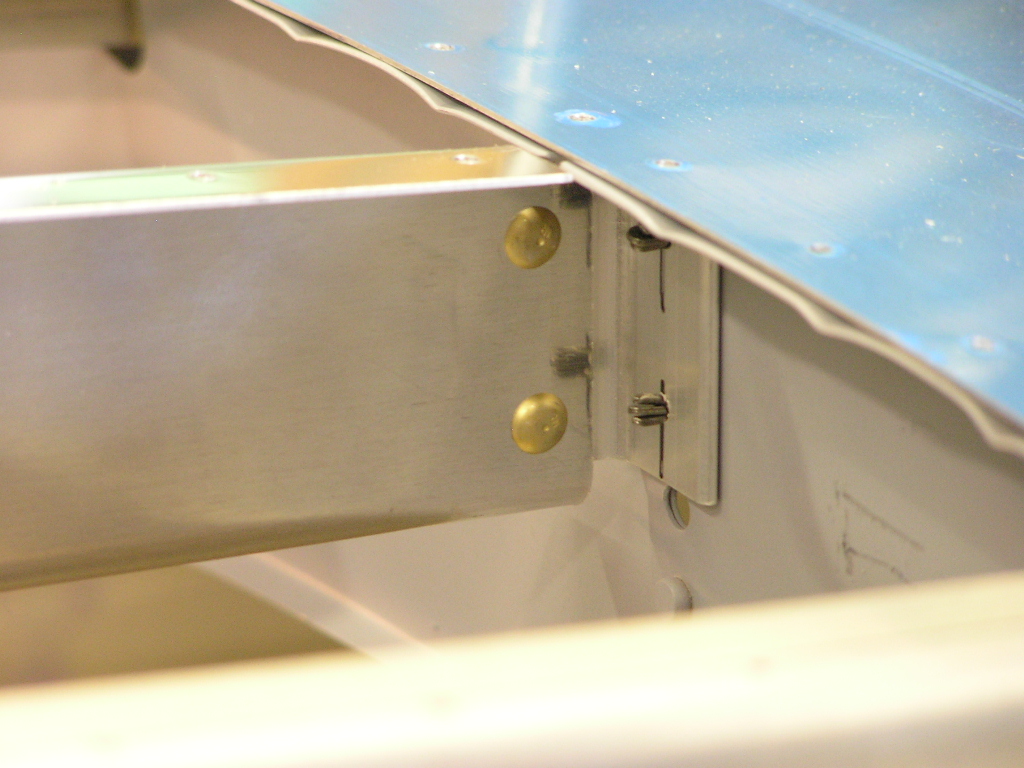
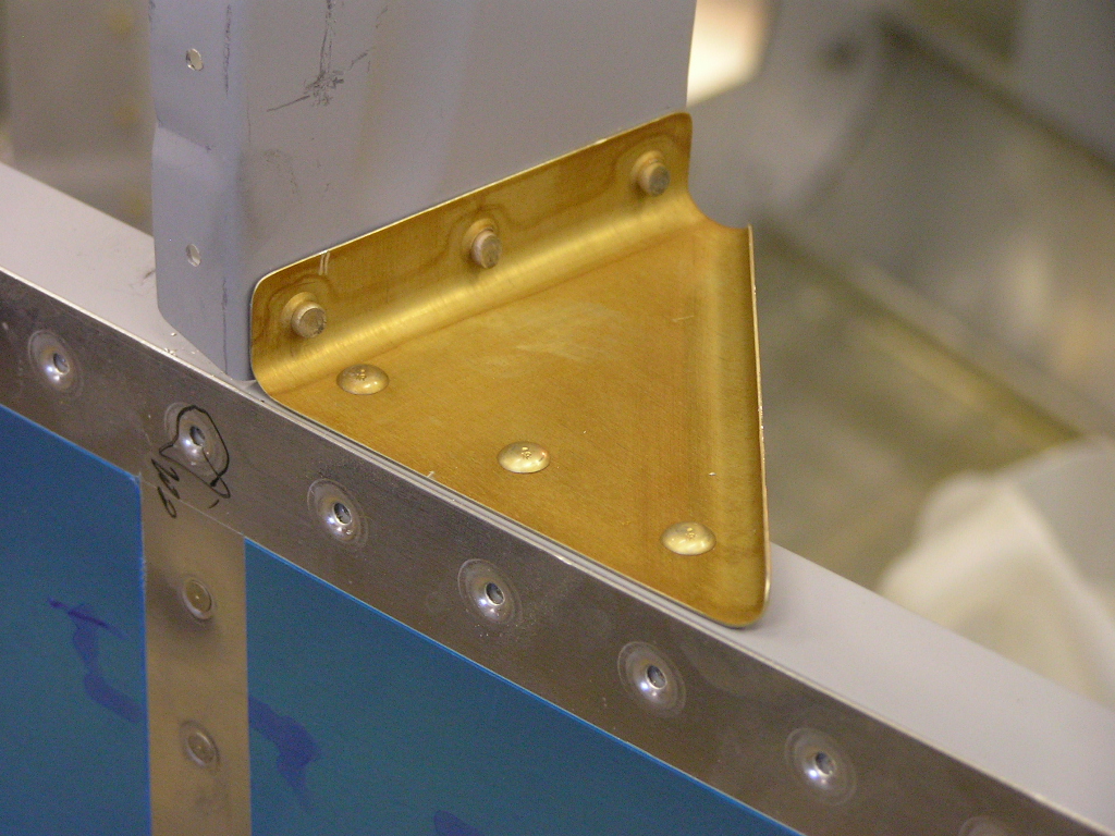
| 9/9/07 | Thanks to fellow builder Mike Bullock, he had
an instruction sheet from TruTrak which HAD the 2.80" dimension
I needed.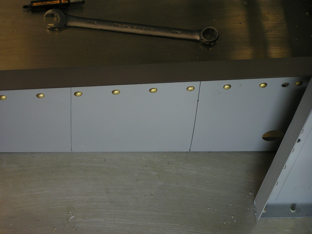 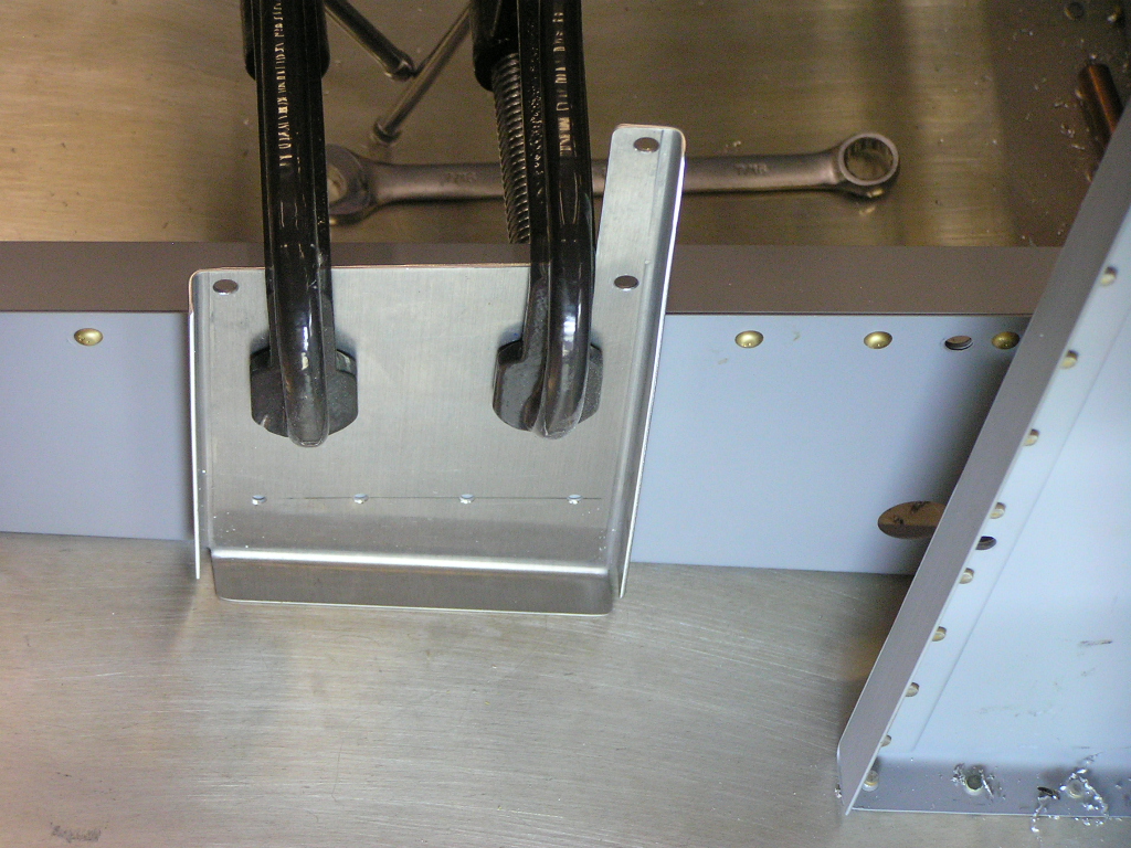
I decided against drilling and riveting through the bottom skin
so I added a second row of rivets near the bottom of the
bracket. 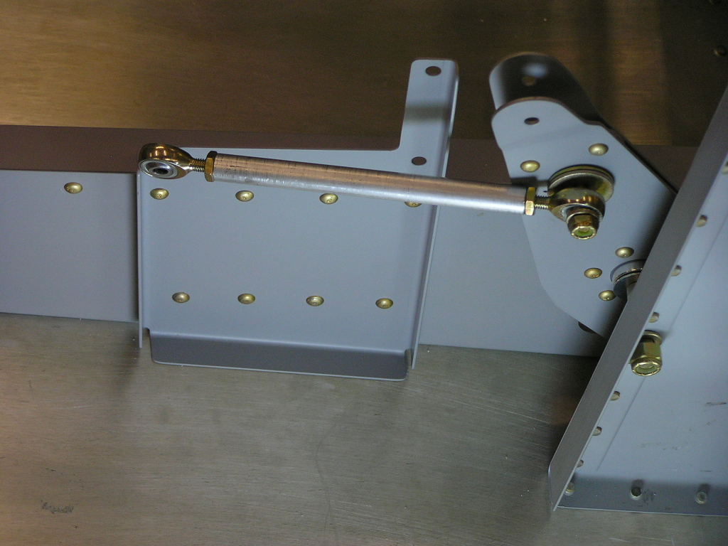
I dimpled and installed the platenuts for the tunnel cover as
well as the control access in each front seat floor. |
4.0 |
|
Seat Backs |
||
| 9/12/07 | Trimmed the F-638 Seat Back Brace, drilled the
lightening holes and deburred. I cut the hinge for the
seat back braces and deburred. |
1.0 |
| 9/13/07 | Cut the F-637B angles as well as the F-637C
angles and deburred.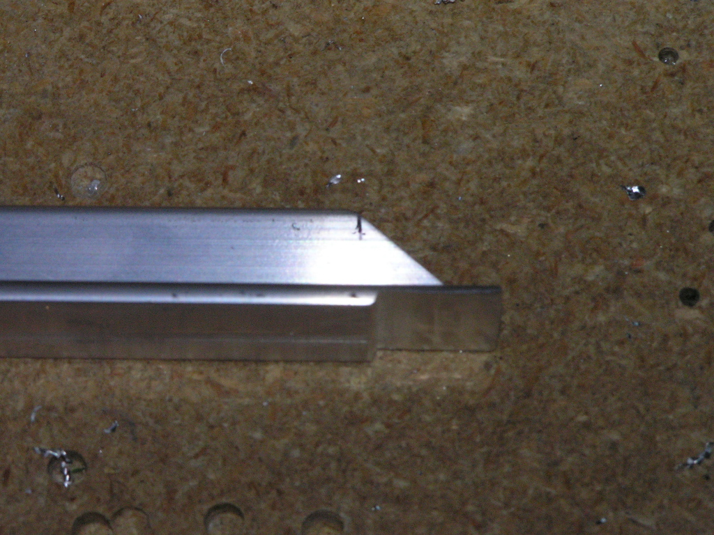 |
1.0 |
| 9/14/07 | Finished fabricating the angles and hinges for
the seat backs and deburred. Drilled the hinges to the
seat back braces and deburred.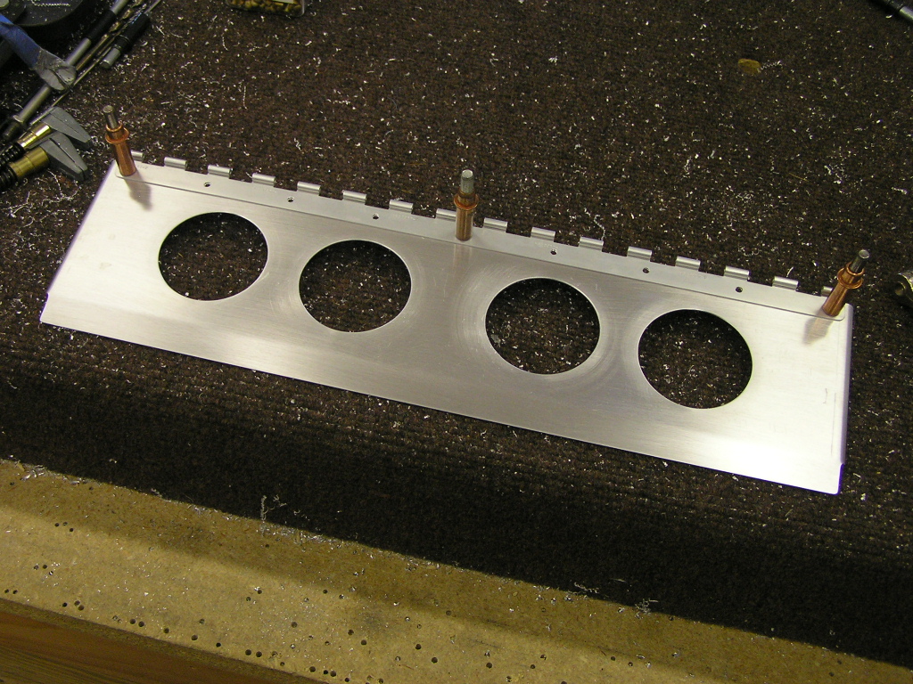 |
2.0 |
| 9/15/07 | Finally drilled and assembled the seat backs
and clecoed together. This project took an amazingly long
time but I tried to get these things right. All in all I'm
happy with them. We'll see how they look after they are
riveted together.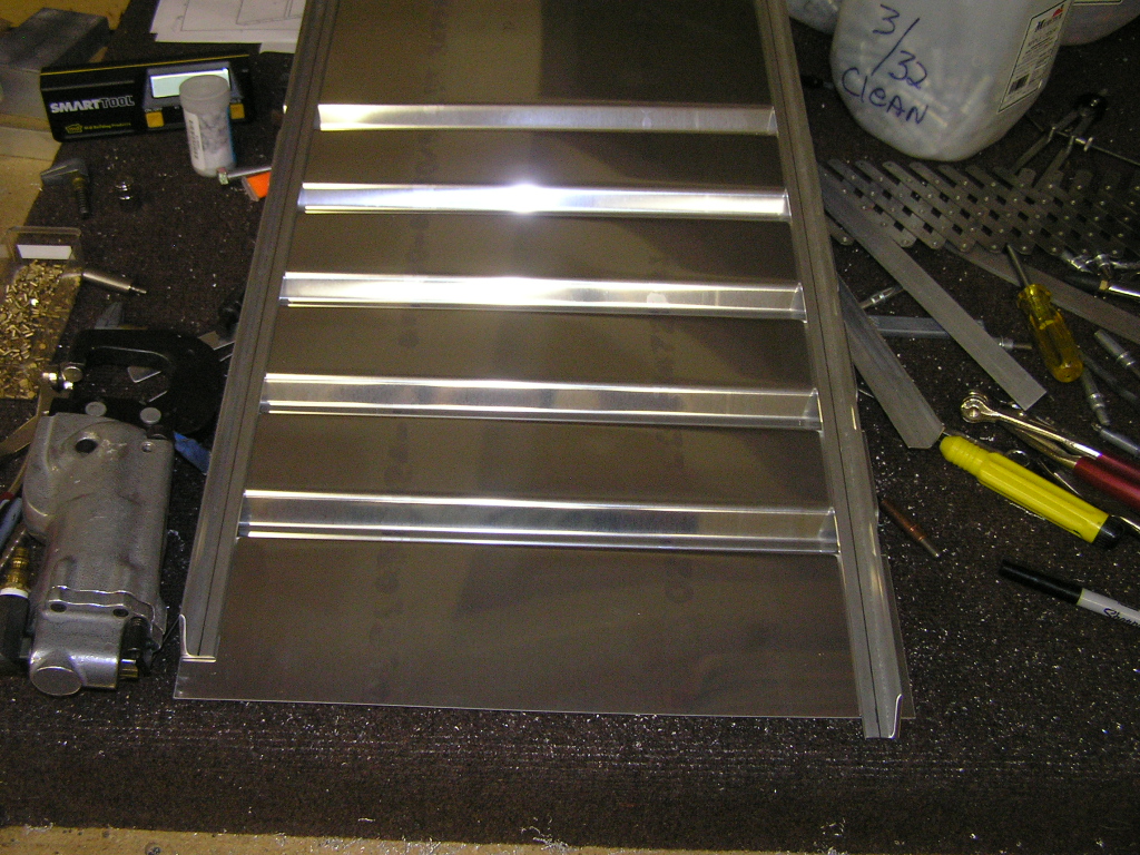 |
4.0 |
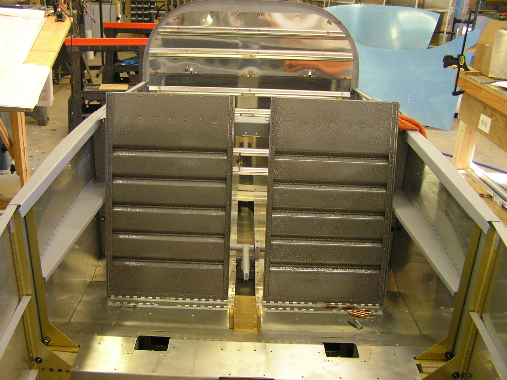
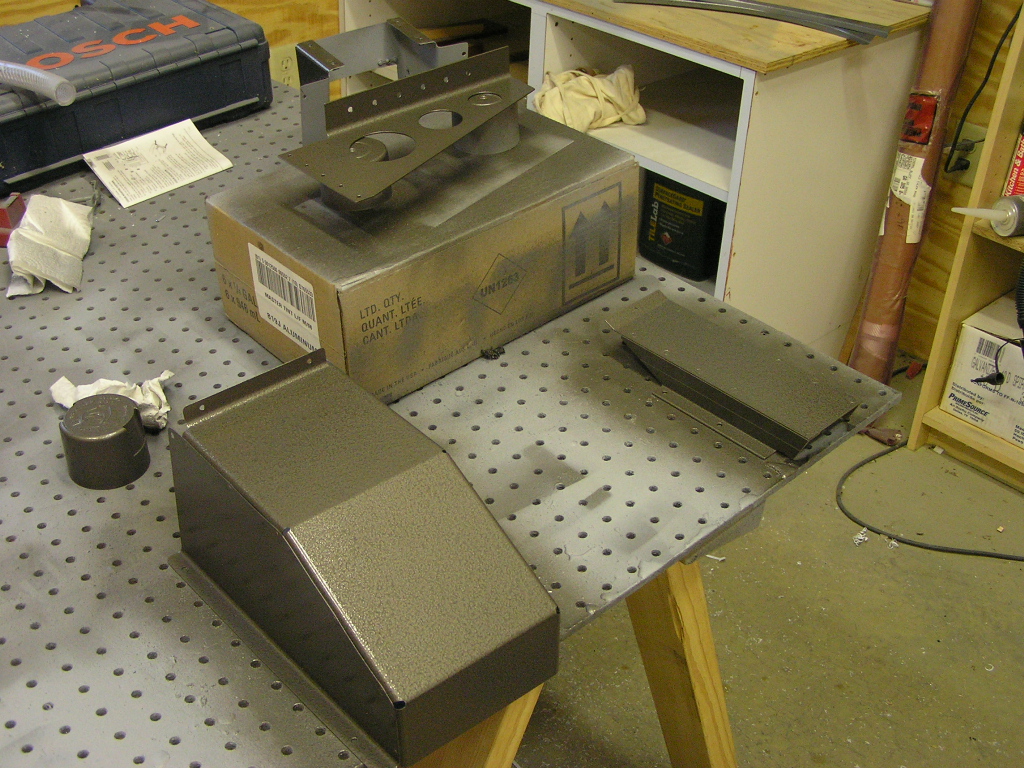
| 9/16/07 | I scuffed and washed the seat back components
and riveted the components together. After both were
assembled, I spray painted with the hammered gray enamel.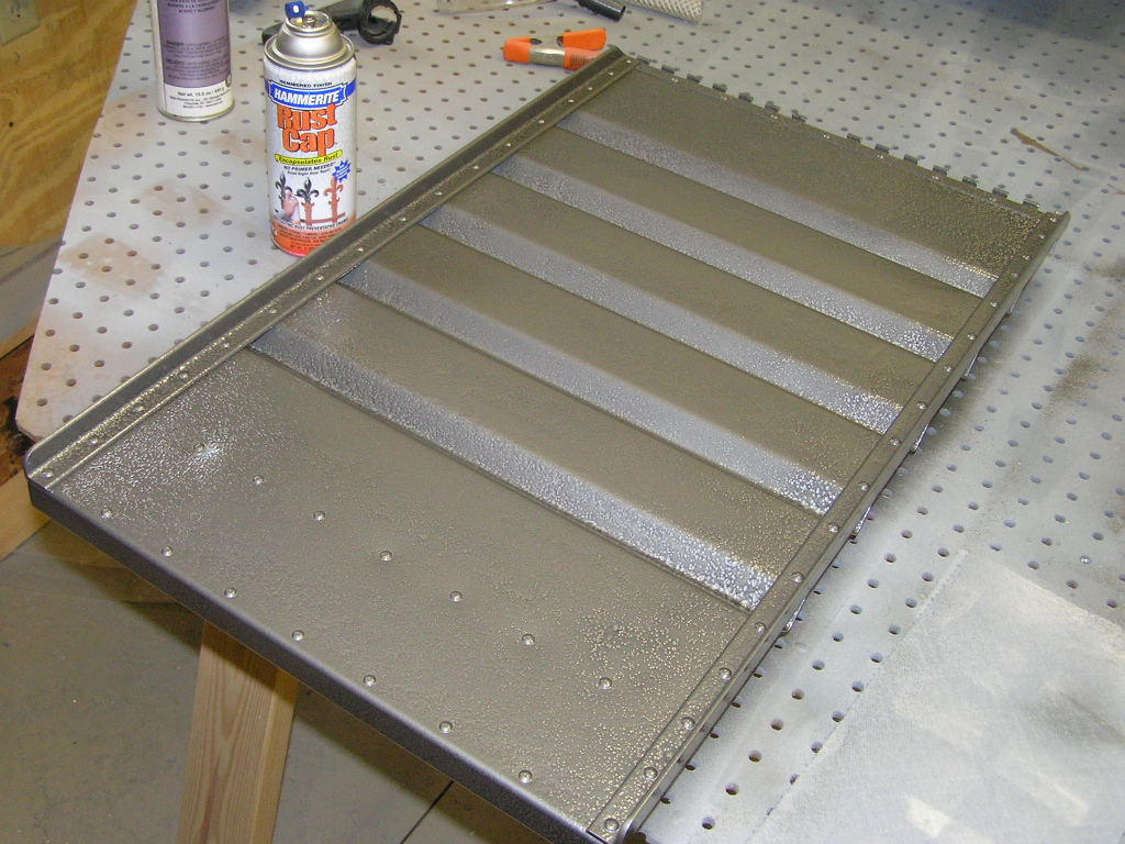 |
4.0 |
|
Forward Covers |
||
I fit the F-982E Access Plate and F-982D Heat
Baffle to the F-981C Center Cabin Cover and drilled to full
size. I disassembled and deburred the holes and
components. Dimpled for the rivets and platenuts. |
1.0 | |
| 9/17/07 | I got a call tonight that my Father had died.
He had been slowly deteriorating for the past 9 months as a
result of COPD in his home in Dale, Texas. I spent the
next week in Texas attending to his affairs. I wish all of
you could have met him. He was a great person and my
greatest cheerleader. I will miss you Dad. |
|
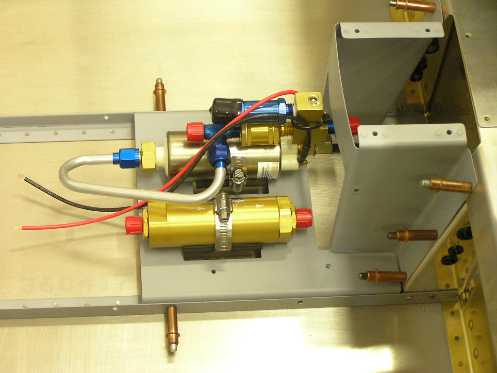
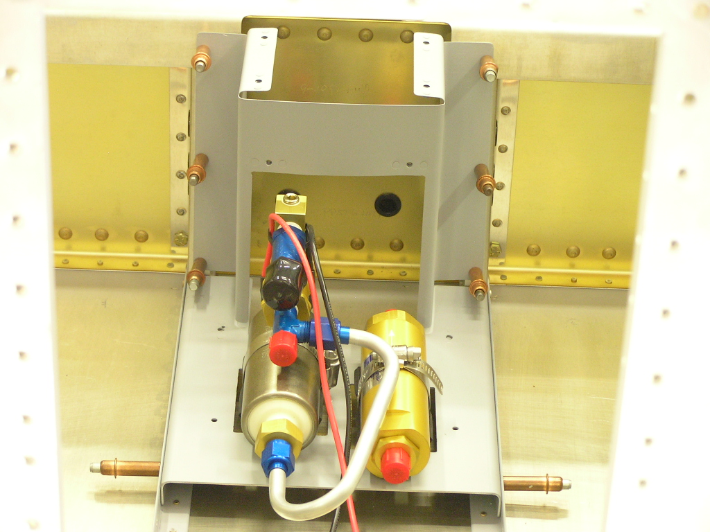
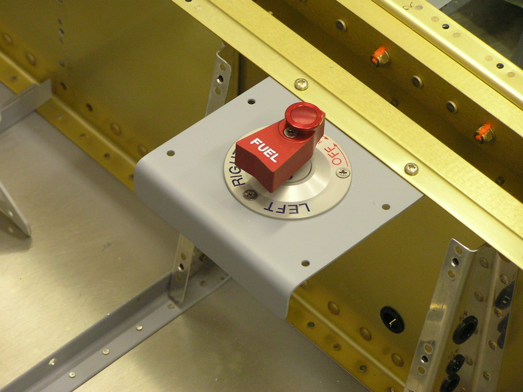
| 9/24/07 | Riveted the platenuts on the F-982E forward cover and
trimmed the F-982C center cover. I am having to deviate
from the plans in order to install the Airflow Performance fuel
injection high pressure pump and filter system. I am also
replacing the standard fuel selector valve supplied in the Vans
kit with the Andair fuel valve.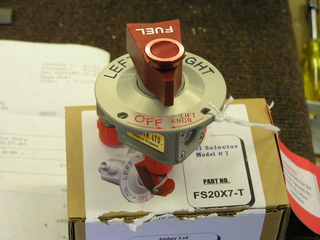 |
2.0 |
| 9/28/07 | I drilled the center covers to the floor
stiffener angles. I riveted the platenuts to the aft
cover. Since I am installing the electric elevator trim, I
will not need the bracket flange of the F-983A Fuel Valve Plate.
While the plans say that the flange can be cut off, this will
leave a large gap at the forward end so I have ordered some
stock T-3 2024 .063 sheet and will fabricate a new fuel valve
plate. |
2.0 |
| 9/30/07 | I riveted the platenuts in the F-7115 and
scuffed along with the other covers. I then primed with
self-etch. I then deburred and dimpled the upper bulkhead
flanges above the longerons.
I began installing the Airflow Performance filter and high
pressure fuel pump but had to stop due to not being able to find
my tubing cutter. |
2.0 |
|
Installing the
Flaps |
||
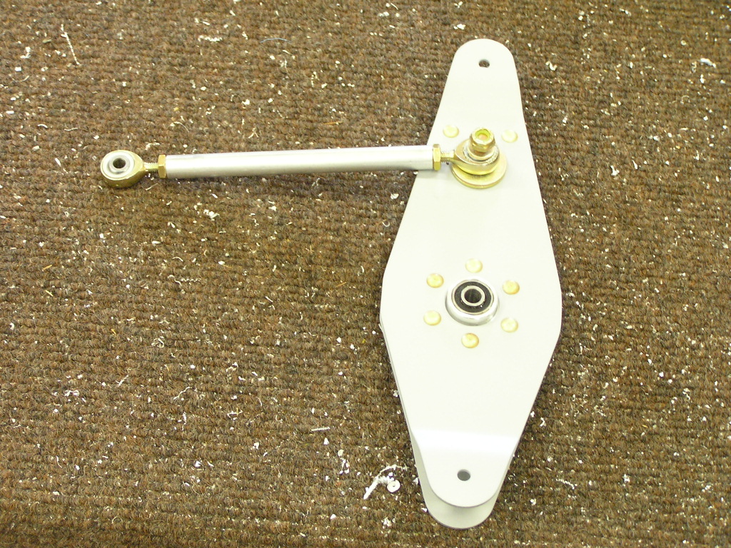
| 9/30/07 | I drilled the clevis ends of the flap actuator
rod to 1/4". I then drilled the flap actuator bearing
end for safety wire. 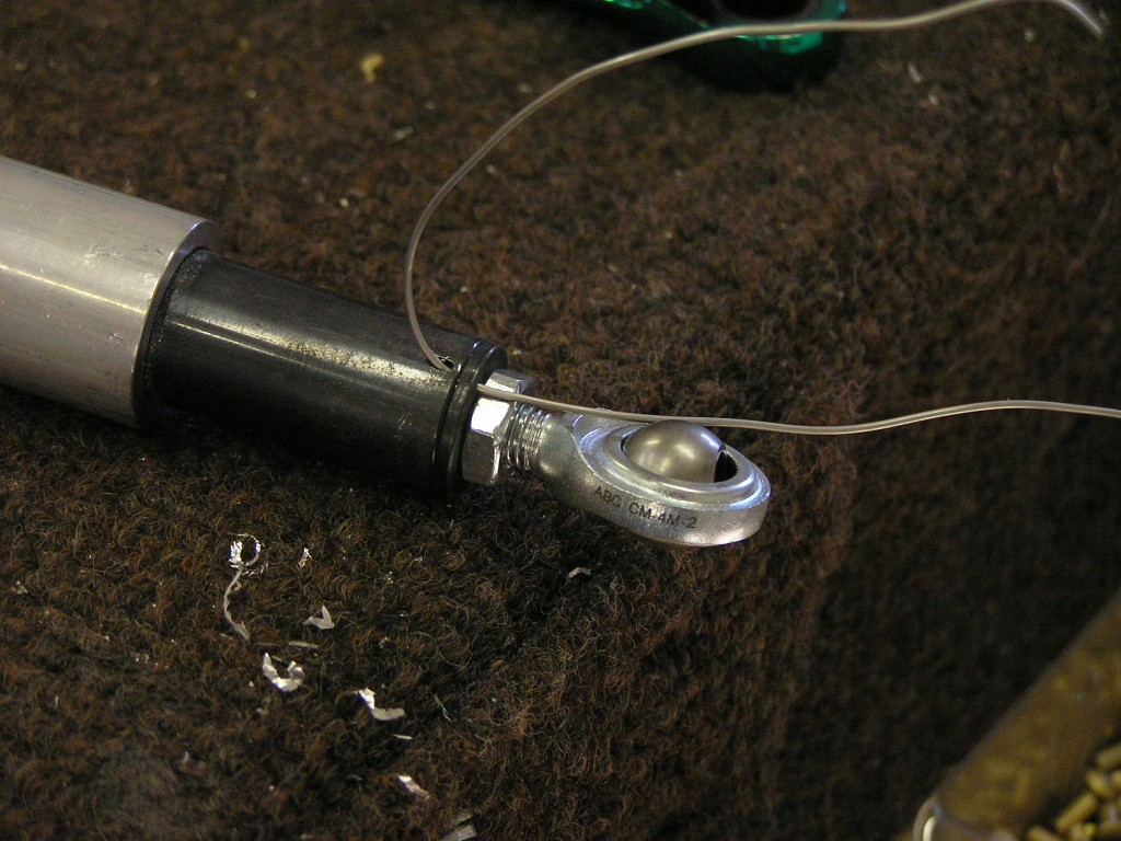 I drilled and cut the center bearing block
and installed the flap actuator rod. |
2.0 |
| 10/5/07 | Tonight I snuck in a couple of hours and
fabricated several brackets and angles for the flap mechanism
including the F-766C Plate, the F-766D Spacer, the F-766B Angle,
the F-767 Attach Plate and the F-785B Attach Angle. I
drilled and deburred the F-766A Flap Actuator Channel and the
F-758 L&R Flap Actuator Brackets. |
2.5 |
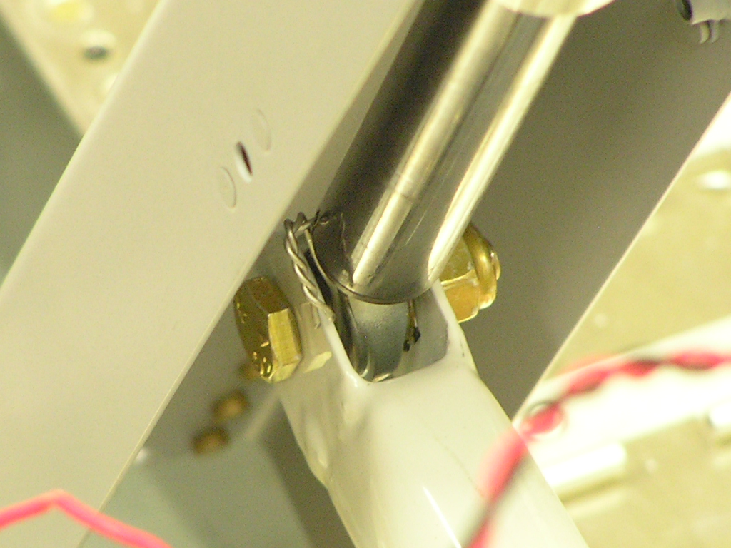
| 10/6/07 | Riveted the F-766 assembly and test fitted it
in the fuselage. I tested the flap motor assembly and
verified that it takes 7 seconds to run
from full up to full down. I attached the flap
arm to the Wd-613-EF actuator arm and safety wired the bolt.
 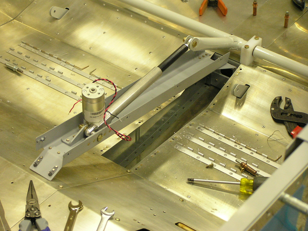 Next, I assembled the motor in the F-766A channel and drilled the
F-766B bracket. After disassembly, I deburred and riveted
the F-766B bracket and re-assembled the flap mechanism. I installed the F-785 Backrest Brace and clecoed the side
covers and match-drilled. I disassembled, deburred and
riveted the platenuts. Finally, I scuffed, primed and
re-assembled. |
8.0 |
|
Landing Gear Mounts |
||
| 10/7/07 | Today I spent a couple hours organizing all the
parts Vans ships in the various parts bags into assortment bins
and labeled. Hopefully I won't be wasting a lot of time
looking for parts. Terry Tibbits,
a fellow EAAer and RV-9 builder, came by to help out. I
have heard from several other builders that it is much easier to
route the fuel lines from the tanks to the fuel selector valve
if you do it before the landing gear mounts are installed.
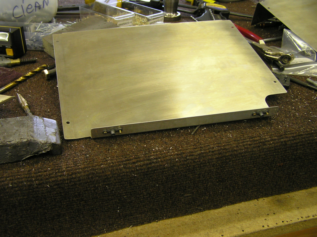
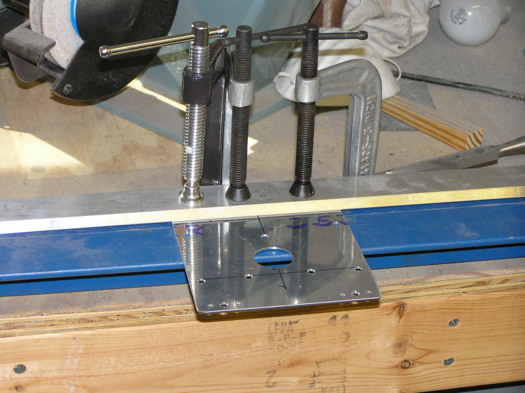
I also have been debating what to do about the F-983A Fuel Valve
Plate. I had cut off the forward section since I will be
using electric trim, unfortunately, this leaves an ugly gap
where the forward edge meets the F-983C Fuel Valve Cover.
My solution was to make another fuel valve plate out of .063
with a 1" forward lip. Terry cut the plate, match-drilled and bent the lip with the
sheet metal brake. It fits perfectly with the Andair Fuel
Valve. Oh, did I mention that Terry is an A&P?
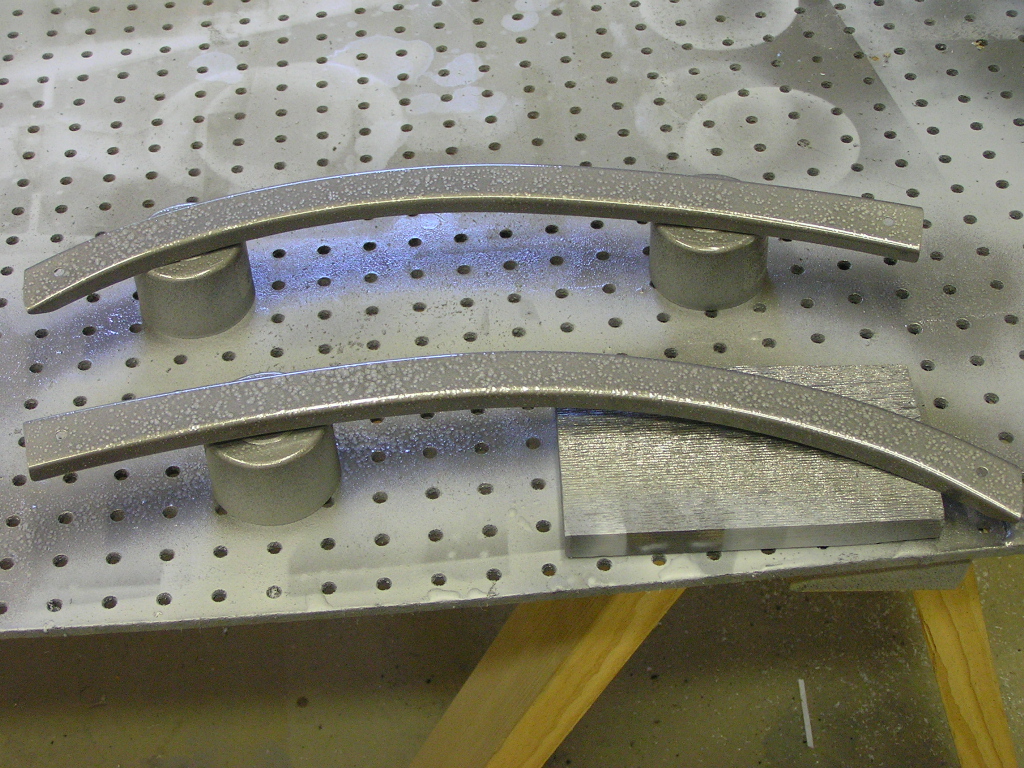
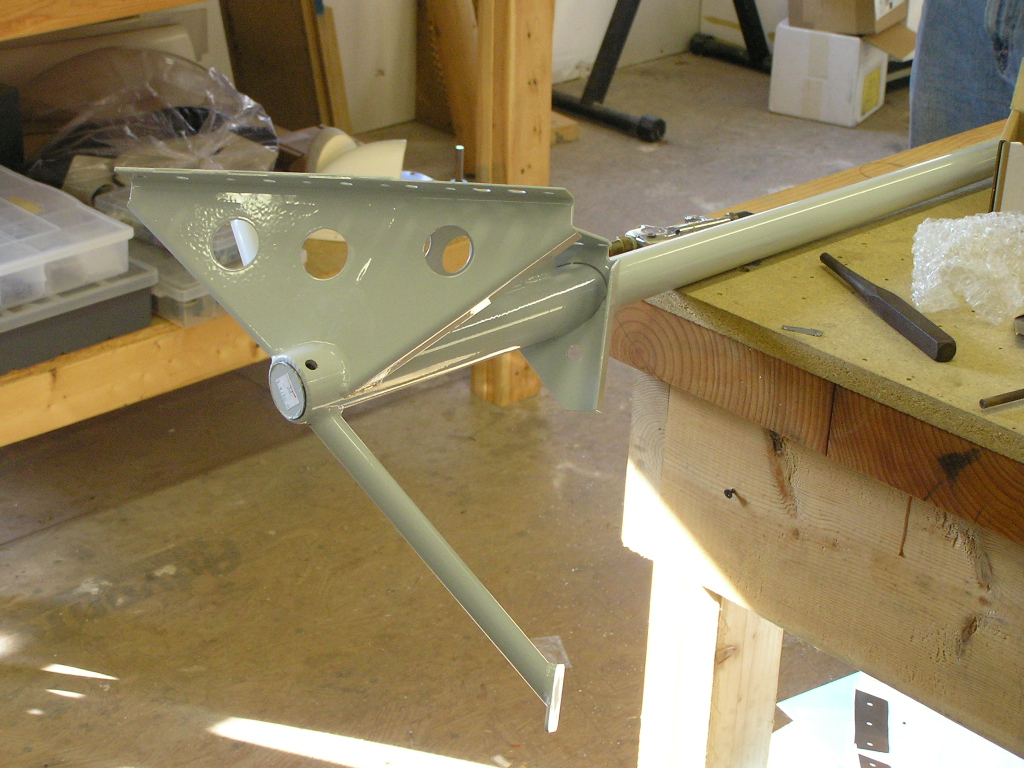
You're welcome to come by and help anytime Terry. Next, before the landing gear mounts can be installed they
have to be match-drilled with the landing gear legs. The
plans say to drill with a .311 bit... Whoever heard of a .311
drill bit? We
drilled to 5/16" and deburred.
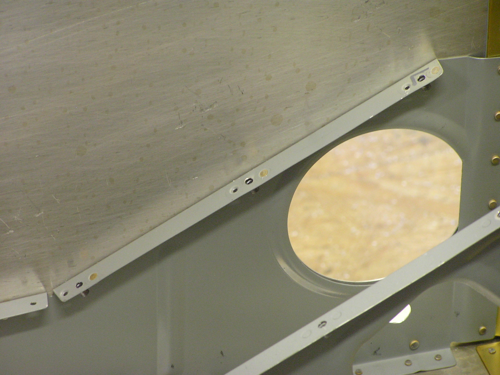
When trying to fit the mounts through the hole in the floor we
quickly discovered they would not fit. I had cut the holes
way back when I was deburring the floor skin and the plans state
that the hole will need to be "tweaked" in order for the mounts
to fit. |
6.0 |
| 10/10/07 | Tonight I worked on trimming the holes in the
bottom skin where the gear mount exits using the Dremel tool. I would trim a small
amount, deburr the hole and test fit, then trim some more,
deburr and test. I finally got the mounts to fit but saw
that the attach points that bolt to the spar was interfering
with the floor stiffeners. these will need to be trimmed
and then I will need to see how they fit. This is a
tedious process but the landing gear mounts have about 10 bolts
that pass through them so the fit must be perfect in order for
the holes to align correctly. |
2.0 |
| 10/12/07 | I used the Dremel to grind the floor stiffener
to allow the landing gear mount to fit flush against the spar
and side skins.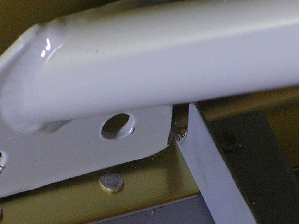
Before I mount the gear leg mounts permanently I will install
the fuel lines which route through the gear legs. |
2.0 |
|
Installing Cabin Systems
(Brake Lines, Fuel Tank Vent and Fuel Systems) |
||
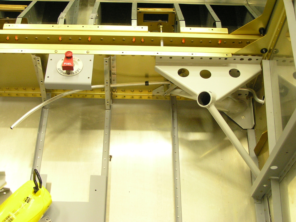
| 10/12/07 | I began the process of installing the fuel
lines by straightening a length of 3/8" AL tubing and cutting
two sections 36". |
1.0 |
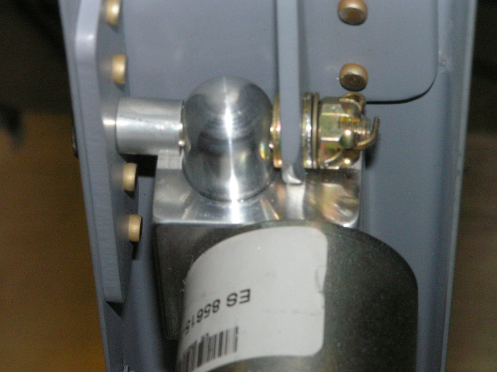
| 10/13/07 | I received a shipment from Abby at
Flightline Interiors a few days ago. I had ordered
some firewall insulation blanket as well as the aileron boots.
I cut the pattern for the attachment ring out of some scrap .040
and cut the inside using my saber saw. After deburring, I
drilled to the fuselage and installed platenuts on the rings.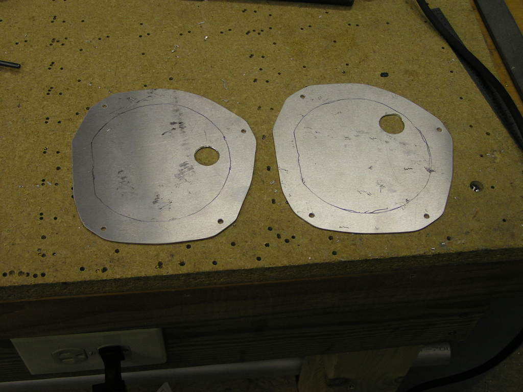 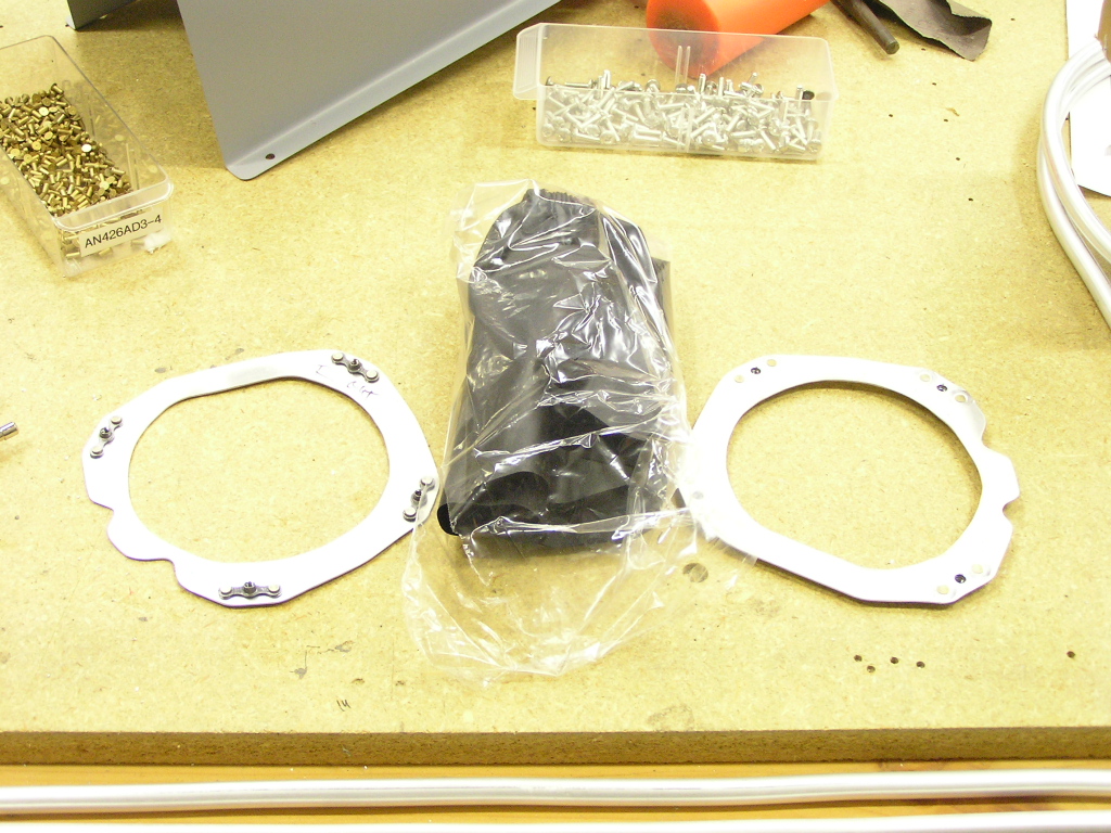 |
1.0 |
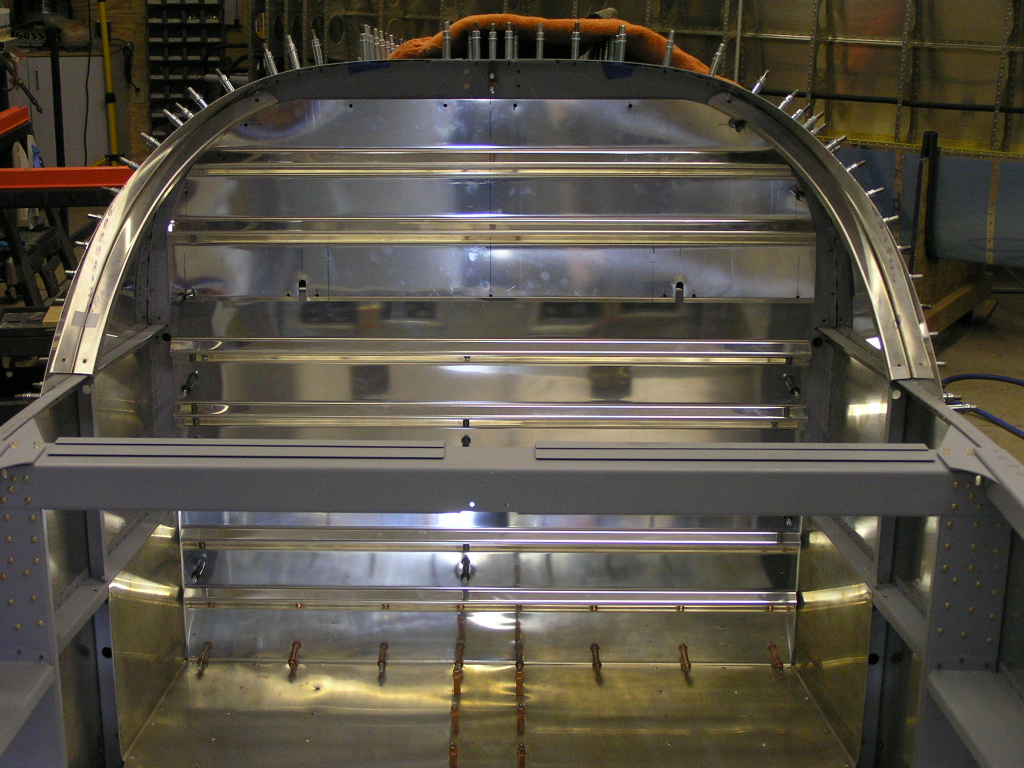
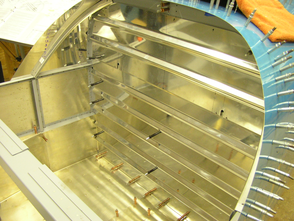
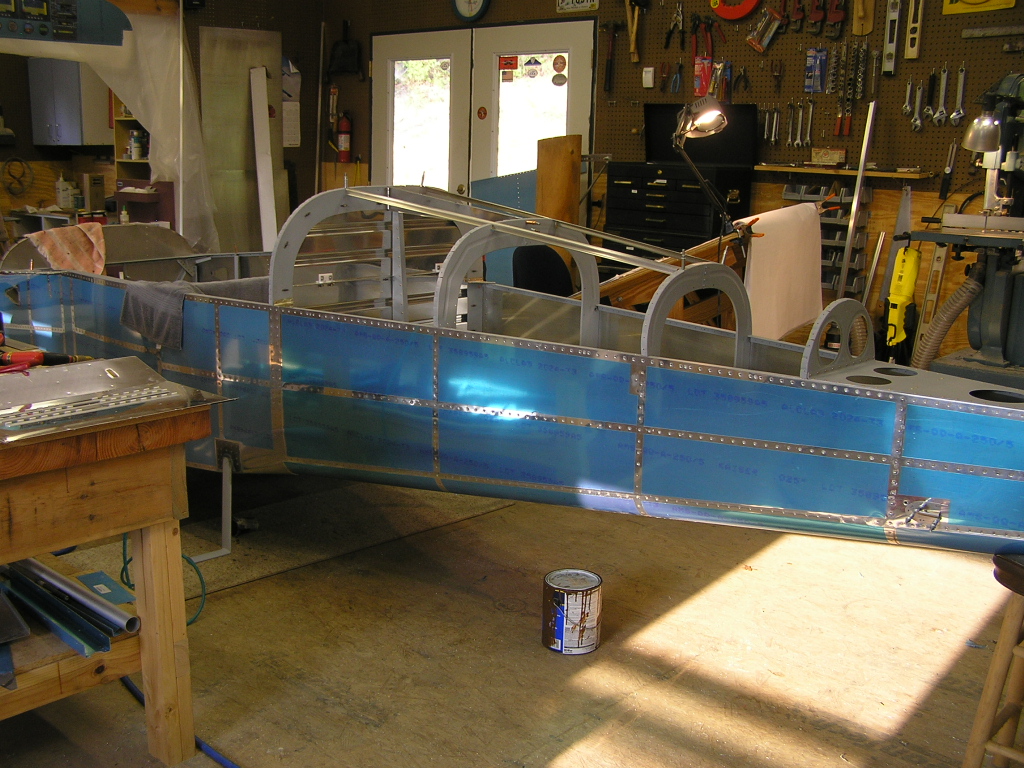
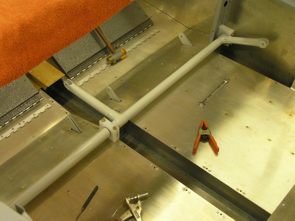
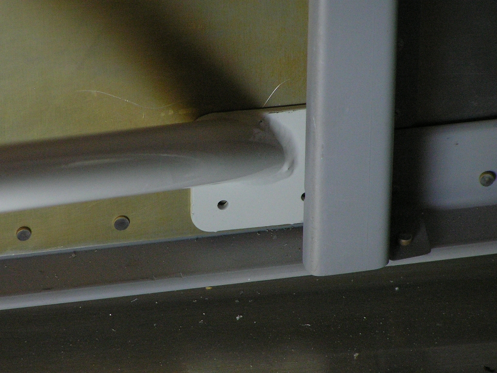
| 10/14/07 | I had been having the fuselage sitting on two
plastic milk crates so I covered a piece of 1x12 with carpet and
placed it on the milk crates. This will help protect the
bottom skin and allow me a stable platform for crawling inside
the fuselage.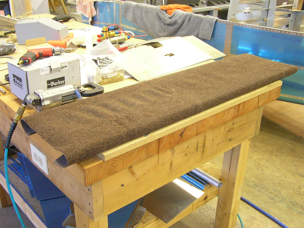
While taking a break, I decided to shoot a few forward covers
with the Rustoleum hammerite paint.
I installed the left fuel line by first bending the 3.5" "jog"
and then running the tubing through the landing gear mount, then
the small cover bracket, then through the cover bracket riveted
to the spar. I then slid the outboard section through the
hole in the fuselage and slid the gear leg mount into place. |
2.0 |
| Riveting Bottom
Wing Skins In preparation for fitting the wings to the
fuselage, I need to finish a laundry list of details on the
wings including installing the Gretz pitot line and electronic
control unit (ECU) as well as pulling the various wiring and
antenna coax. Details can be found
here. |
||
| 10/27/07 | I took some time off from building since my Mom
and Aunt came to visit from Texas. Tonight I jumped back
at it and ran the rudder cables. I took another builder's
advice and ordered some cable protective covers from
West Marine.
The covers are 5/16 diameter and wrap around the cables to
prevent chafing.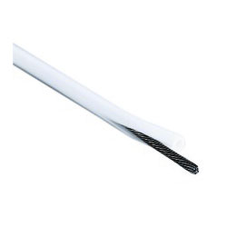 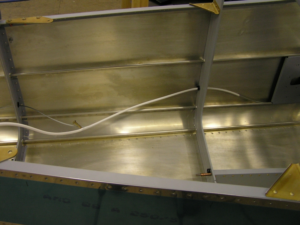 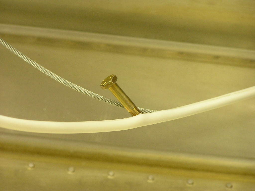 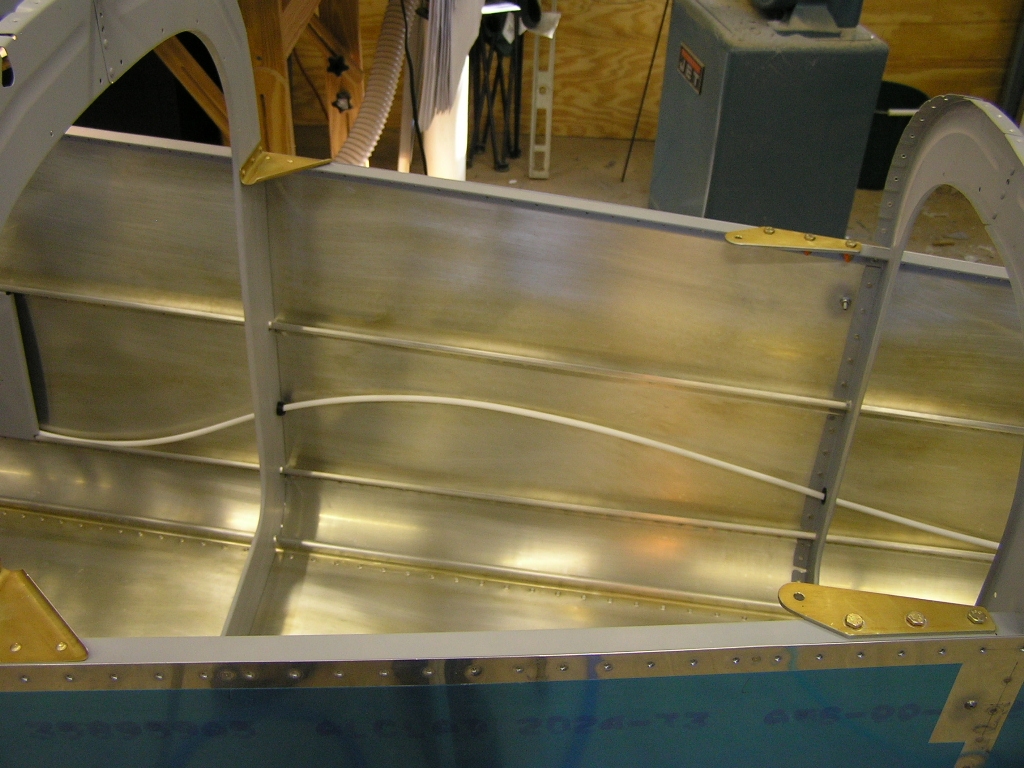
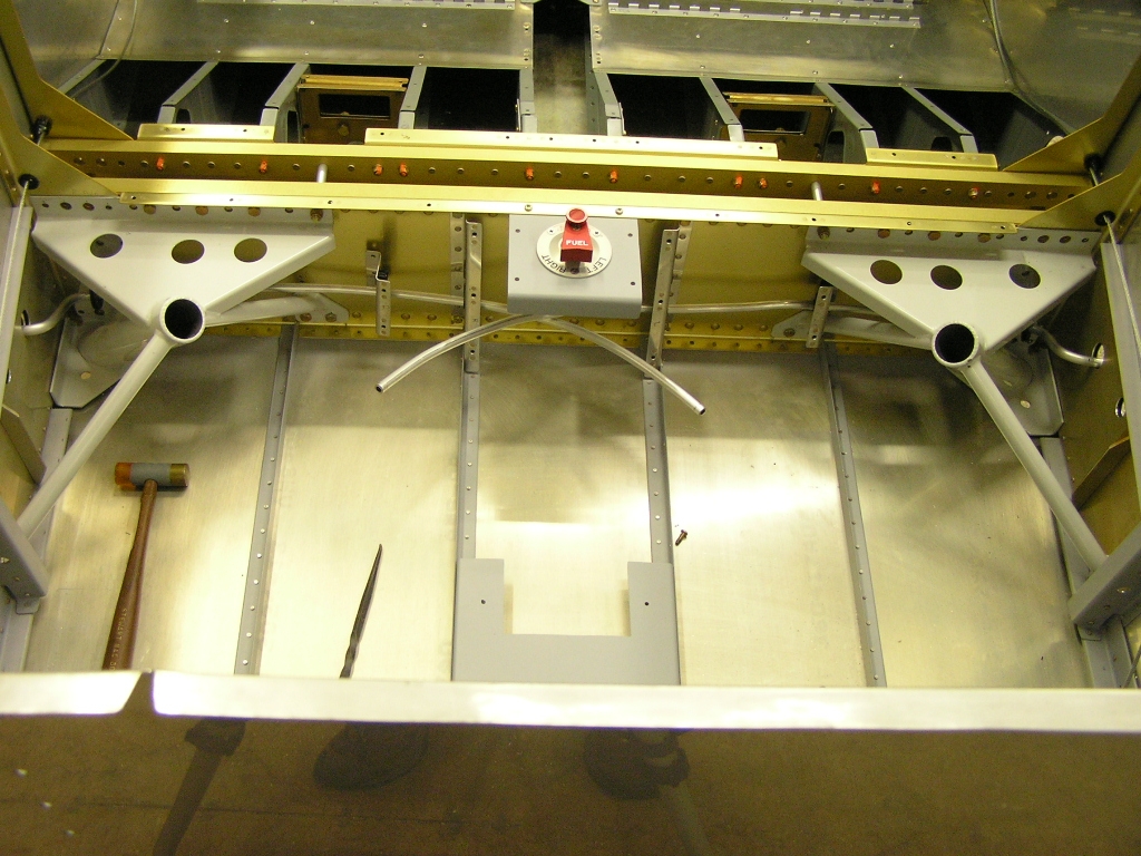
I also installed the right fuel line from the tank through the
gear mount to the fuel selector. I then got a good start
bolting in the gear legs. The Plans call out AN4-12A bolts
through the gear mounts but even with thin washers there is not
enough thread showing past the nut. I used AN4-13A bolts
and the problem is solved. |
2.0 |
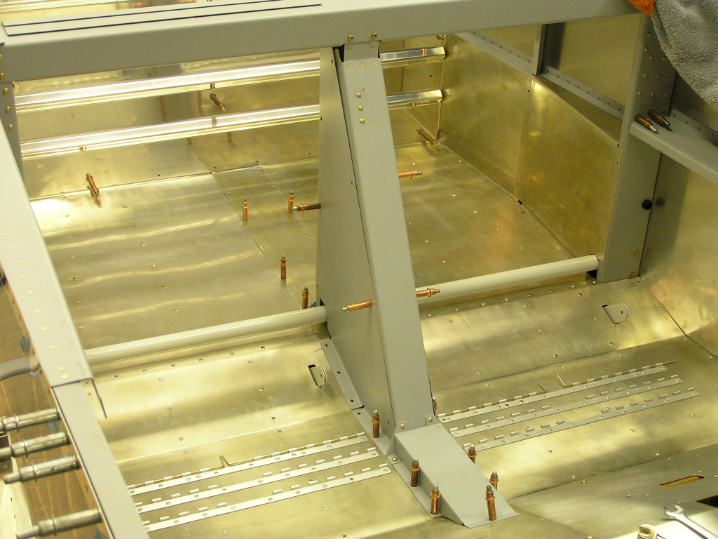
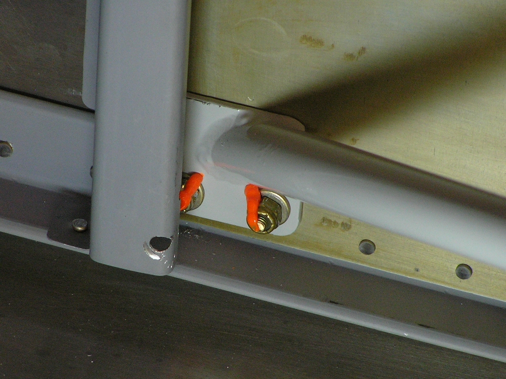
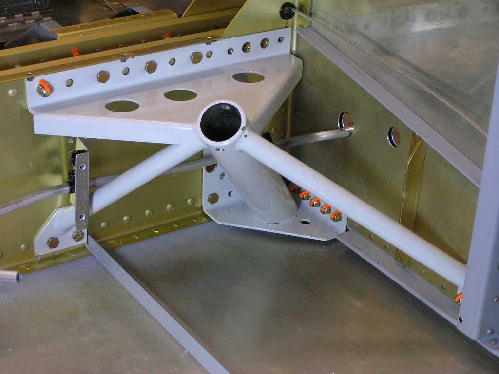
| 10/28/07 | I needed to get the gear mounts installed so I
could work on the wing wiring. I bolted the mounts to the
center section first and then drilled and back-drilled the side
attachments. The bottom bolts through the center section
were tough to reach but I used a long hemostat clamp to get the
washers and nuts started.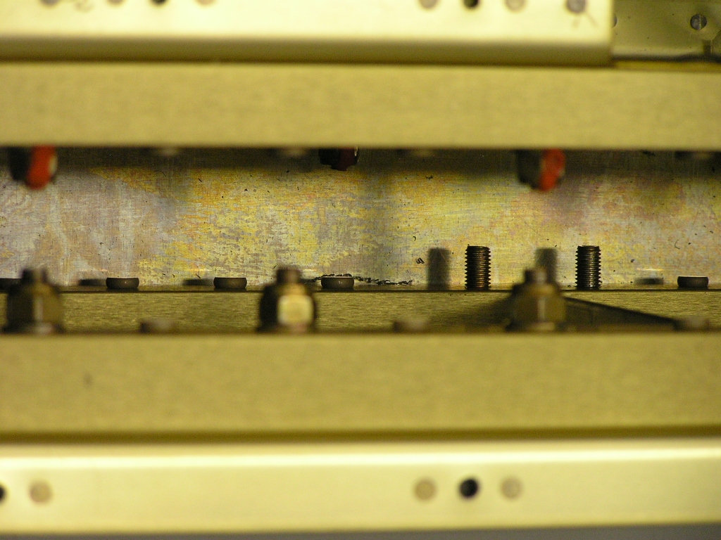
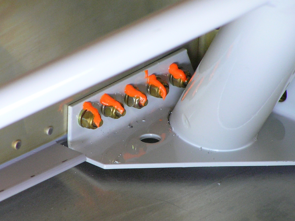
One hole on the side brackets was obscured by the bulkhead
flange so I just drilled through it. These holes are
drilled in assembly so once they were drilled (#30) and opened
to full size (3/16"), I was able to install the AN3-6A bolts. Finally, I back-drilled the five lower mount side attachment
holes and installed the bolts and torqued. I will be jumping over to the
wings now but
will be back in a few days. |
4.0 |
| 11/3/07 | While waiting on my riveting partner, Terry, to
arrive to rivet the wing bottom skins I worked on several tasks.
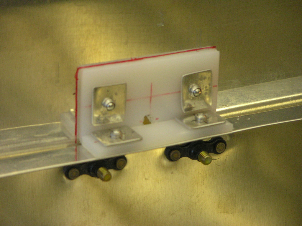
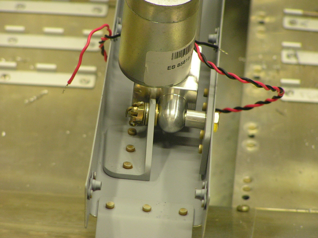
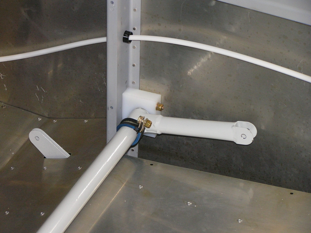
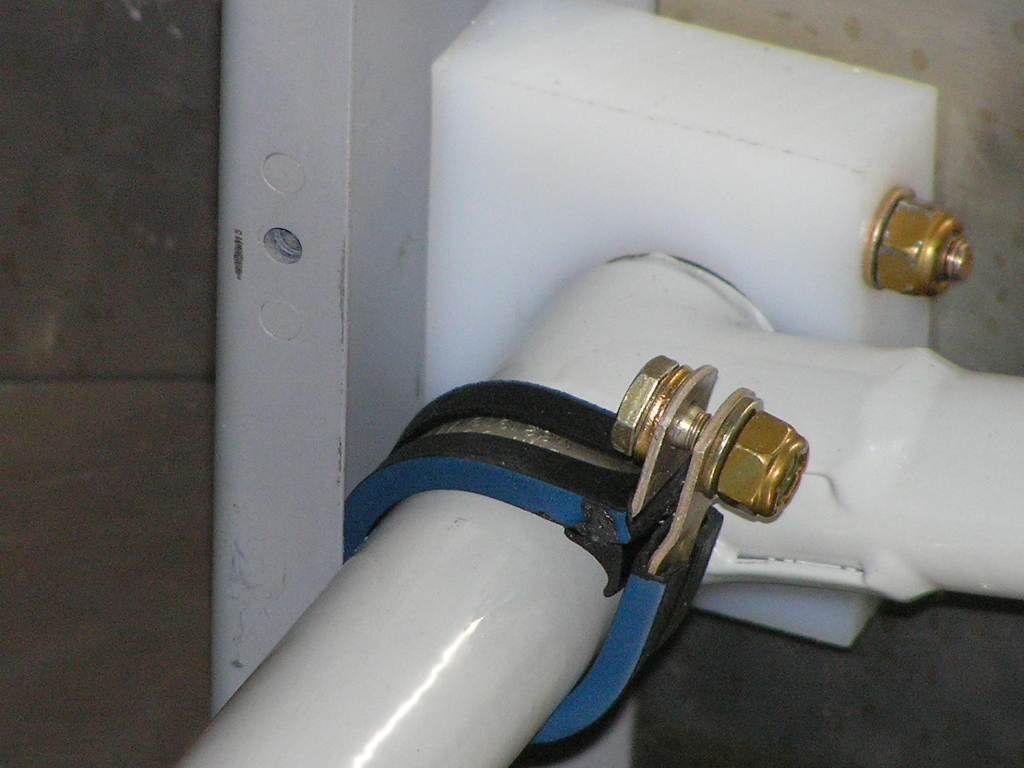
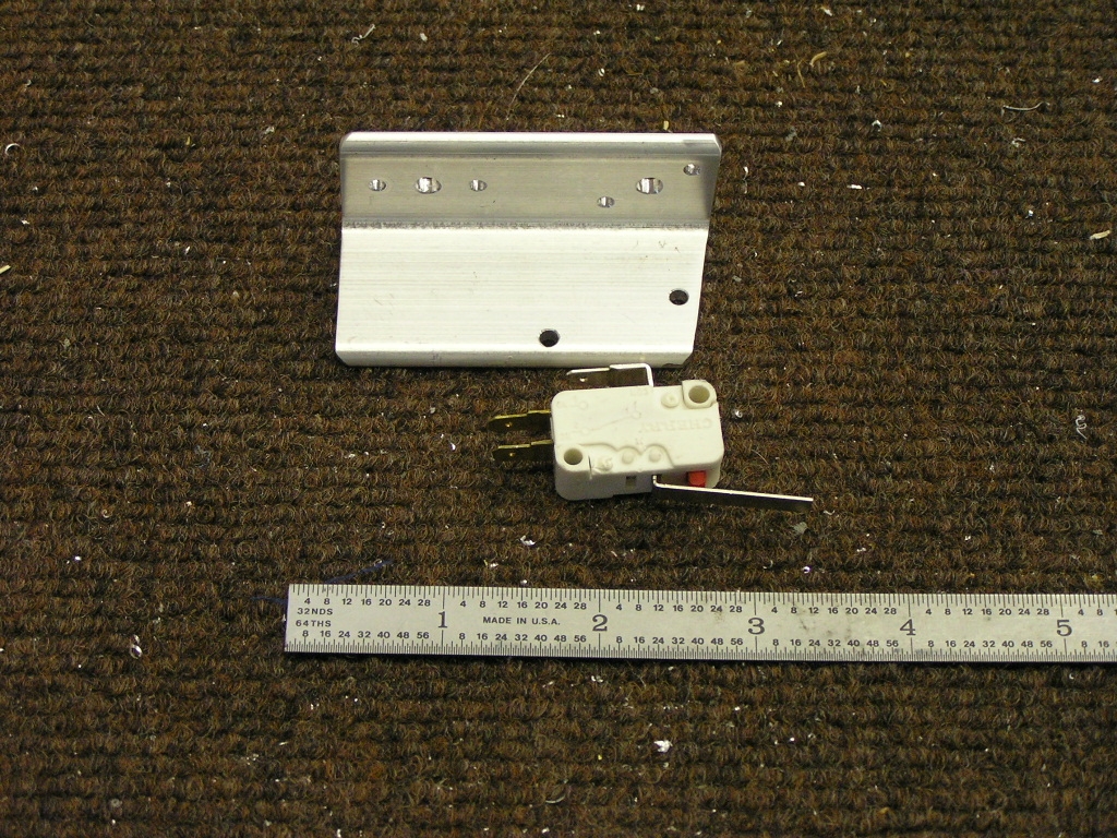
I also started dimpling the aft top skin.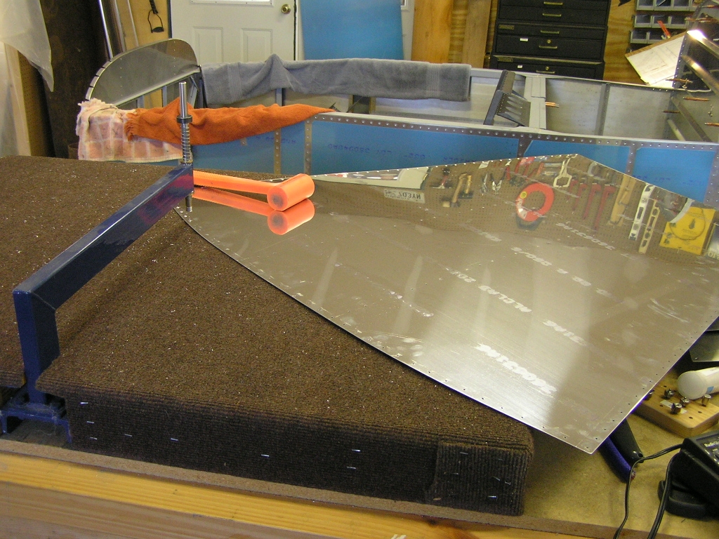 Elevator Servo Speed Controller Switch I began fabricating a bracket for the micro switch near the
flap actuator rod that will control the
Ray Allen servo
speed control module. The design is pretty simple and will
use an Adel clamp around the flap actuator rod which, when the
flaps are fully retracted (as in Cruise Mode), will activate the
switch which is connected to the servo speed controller.
The result is that the elevator trim servo will run at about
half the speed it does when the flaps are deployed (as in
Landing Mode). I had ordered the lever switch from
Aerocraft Parts and Avionics
so with the Adel clamp installed all I needed to do was
fabricate a bracket to hold the lever switch. I used a
scrap piece of .063 1.0x.75 AL angle and drilled for the switch
as well as platenuts for attaching to the back of the F-905
bulkhead upright. |
2.0 |
| 11/9/07 | I drilled the bracket to the F-904 and attached
the micro switch. It will be several months before I can
wire and test this thing.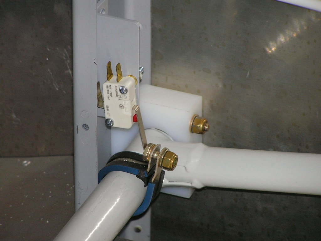 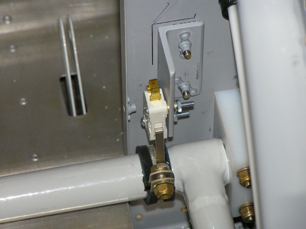 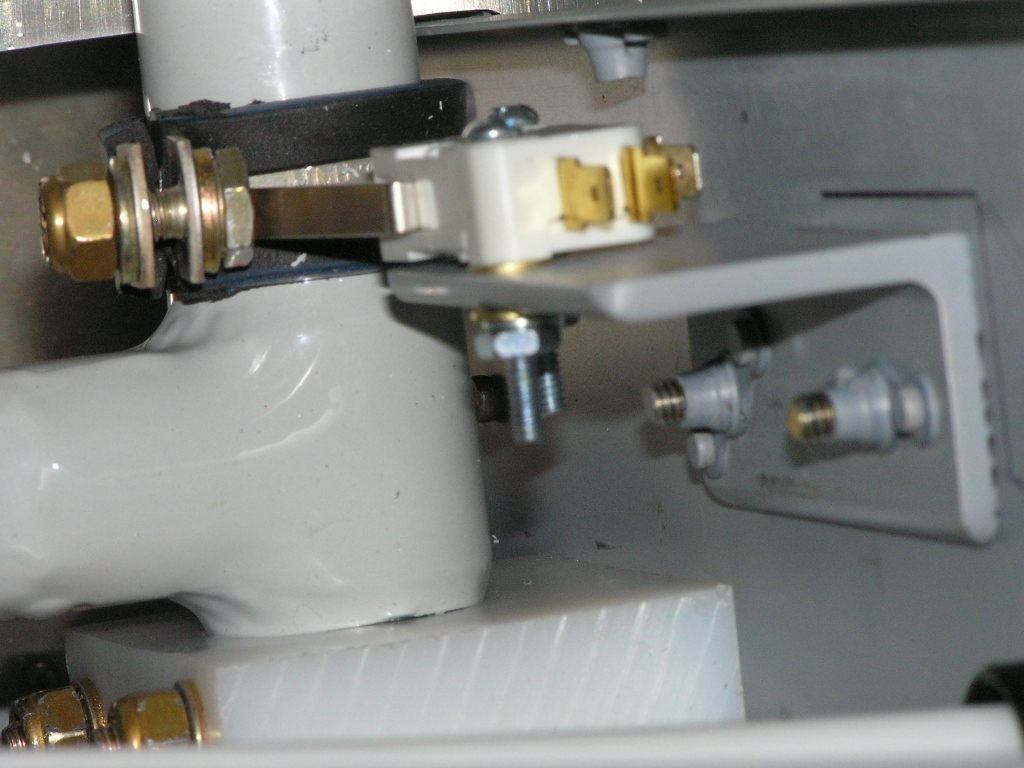 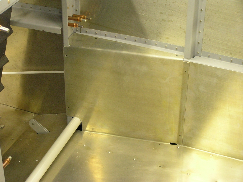 |
.5 |
| 11/4/07 | Today Ben Bierbaum
came up to help me finish riveting the bottom skin on the left
wing. While he was here, Dan Miller, a local pilot and
homeowner stopped by so we moved the fuselage sideways so I can
mate the wings.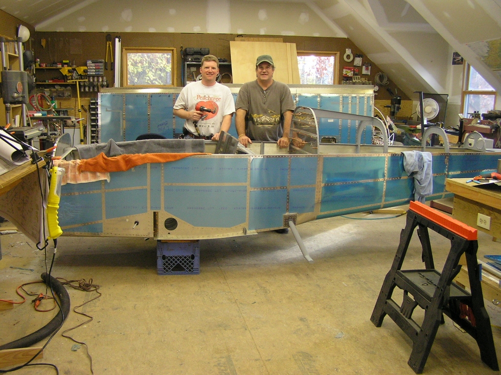 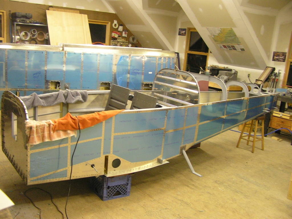 |
8.0 |
|
Total Hours this Page |
91.5 | |
|
Total Hours Fuselage (as of 11/4/07) |
368.0 | |
| Next: Fuselage 5 | ||
Copyright ©2005-07
Hosted by NTI Networks