
Home
Shop
Tools
Empennage
Wings
Fuselage
Panel
Firewall Forward
PC680 Battery Box Install
Engine Mount Install
Exhaust System Install
Alternator Install
Prop Arrives!
Injector Fuel Lines
Soldering Connector Lugs
Fuel Flow Transducer
Fitting the Cowling
Installing Mounting Strips
Installing Cowl Hinges
Pinhole Removal
Oil Filler Door Install
Firewall Forward 2
Canopy
Wiring
Engine
Miscellaneous
Firewall Forward
|
Date |
Description of Task | Hours |
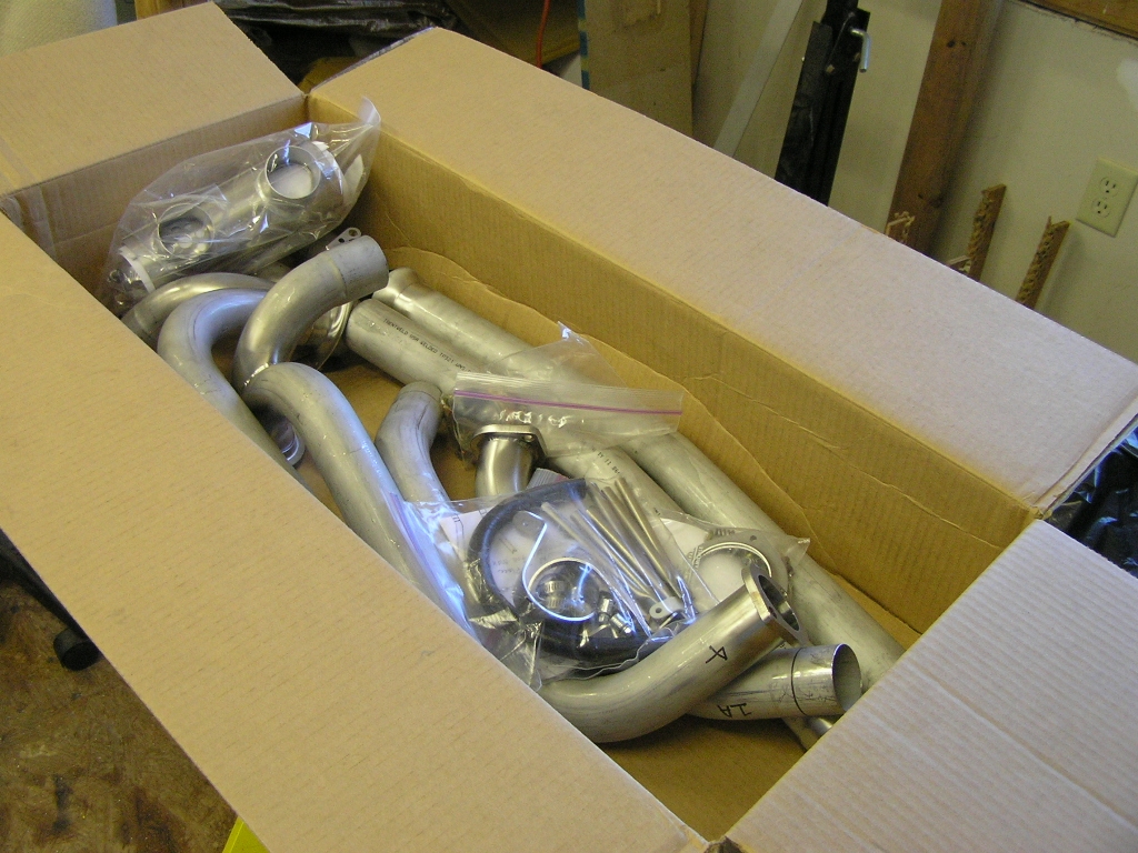
| 3/1/08 | I received my FWF
kit yesterday so today I inventoried.
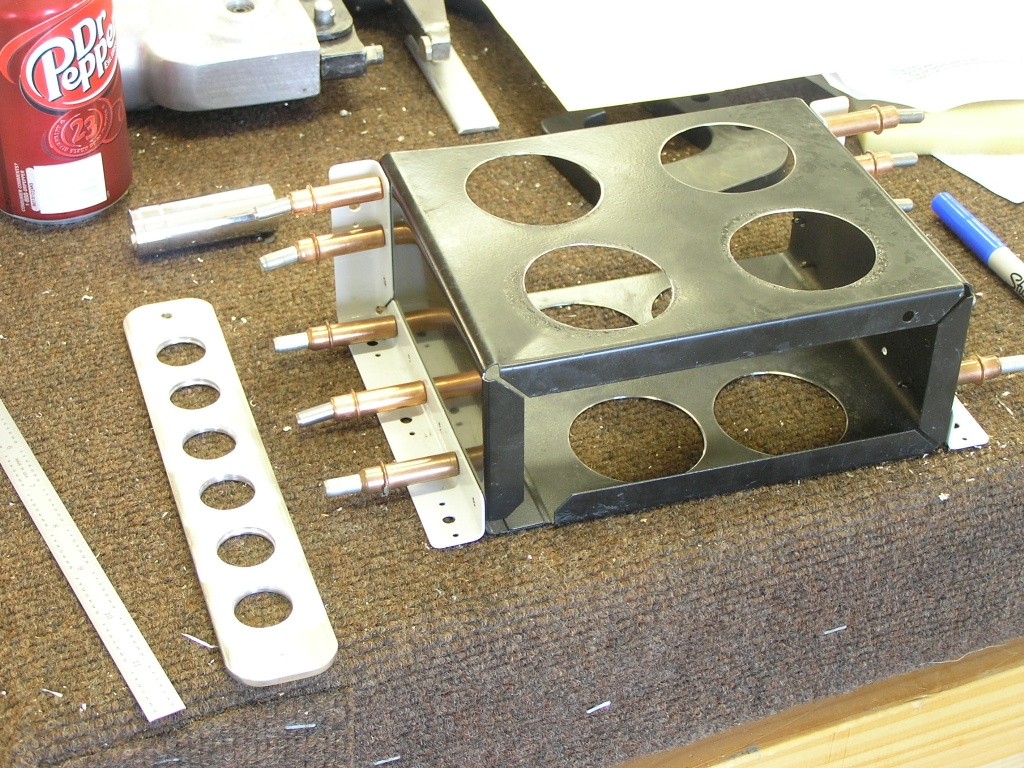
PC680 Battery Box install I started with the assembly of the PC680
battery box. I drilled the 3/4" holes in the battery
tie-down bar and then drilled the 2" holes on the battery box.
After deburring I drilled and clecoed the attach angles. |
2.5 |
| 3/2/08 | Today I scuffed the battery box
and attach angles and primed and painted.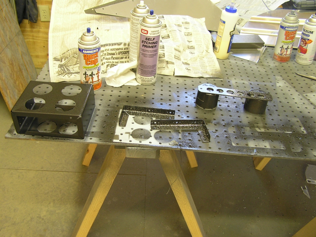
While waiting for paint to dry I went ahead and
drilled and installed the ground "forest of tabs". |
2.0 |
| 3/3/08 | Tonight I finished riveting the
angles to the battery box and installed it on the firewall.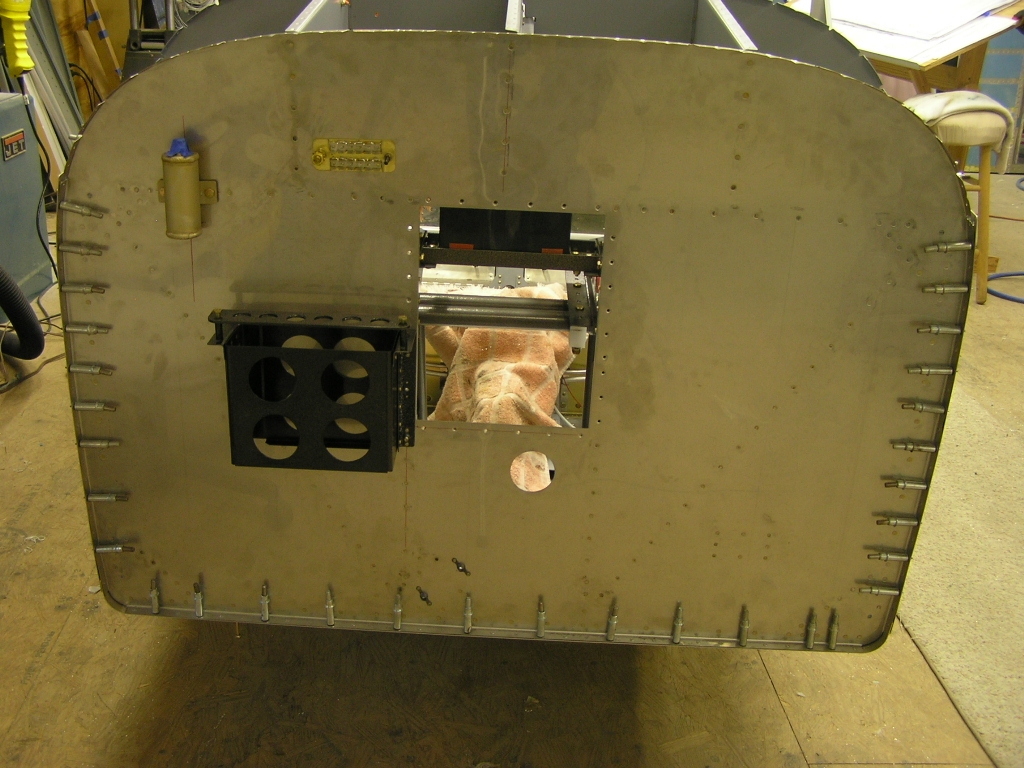 |
1.0 |
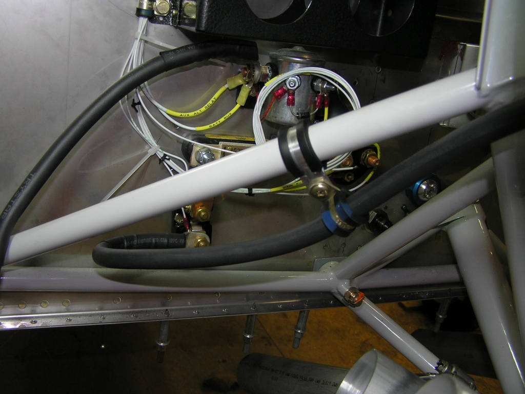
| 3/7/08 | Today I went ahead and drilled
the rivets and additional holes through the firewall in order to
install the B&C battery
contactor and starter contactor. I also fabricated the
doubler plate to support the firewall.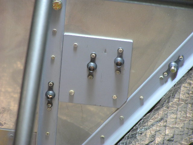 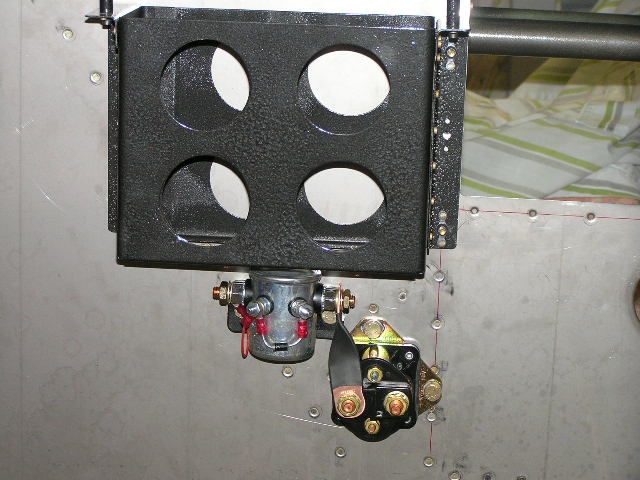 |
2.0 |
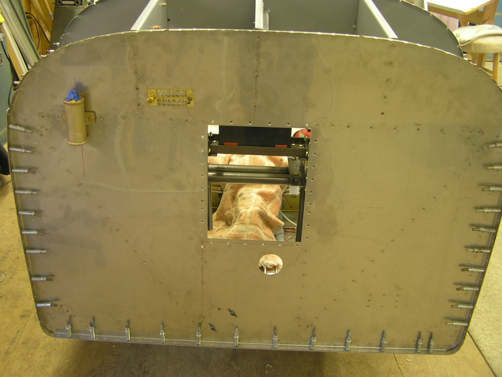
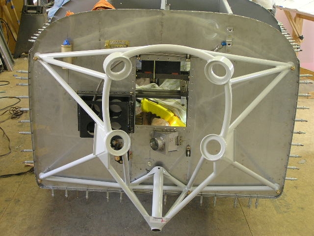
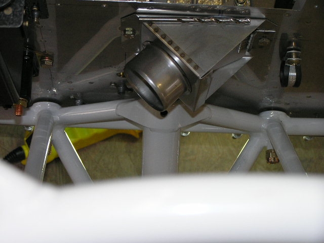
| 3/8/08 | Today I made pretty good
progress. I began by installing the fuel pressure and oil
pressure manifold. Next, I installed the adel clamps for
the oil pressure line along the firewall. I then installed
the stainless steel heater air box. I also drilled the
holes in the firewall for the throttle cable, mixture cable and
the access hole for the nose gear bolt.
Lastly, I went ahead and fitted and drilled
the engine mount. I started with drilling the top left
hole to 3/8" then temporarily bolting the mount to the firewall.
Next, I match-drilled the top right hole and bolted. I
then match-drilled the left and right lower holes and the two
inner holes last. I did not tighten the nuts to final
torque since I will probably need to remove the engine mount
again (hopefully not). The two inside (lower) mount attach points
"stand off" from the firewall about 3/16". I need to
research how others have dealt with this. |
5.0 |
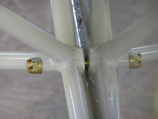
| 3/9/08 | I decided to go the
simple route and fabricated two "square" washers out of .063
aluminum. Worked like a charm.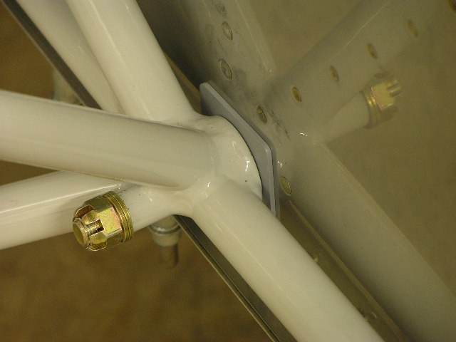
I had heard other builders mention that
the nose gear wheel as shipped from Vans has the wheel bearings
attached to the wheel and has no grease. The problem is
that without grease the bearings can rust. I went ahead
and greased both bearings using Aeroshell
33 multi-purpose grease just to be safe. |
1.5 |
| 3/16/08 | Today I finished installing my
HID wingtip lights.
Afterwards, I installed the ANL 60 fuse
holder and fuse. There are no
instructions at this point so I decided to fabricate a backing
plate for the fuse holder. The holder is very light but
since all other firewall penetrations have doubler plates I felt
it was prudent. I riveted platenuts to the doubler plate
and riveted the doubler to the firewall. Finally, I
fabricated a short piece of copper sheet to connect the starter
contactor to the ANL fuse holder.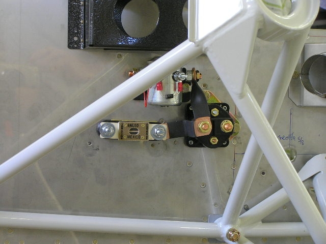 |
2.0 |
| 3/23/08 | I used my hole punch from
Harbor Freight to enlarge the
throttle and mixture cable access through the firewall.
Then I installed the eyeball fittings.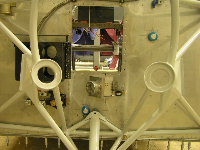 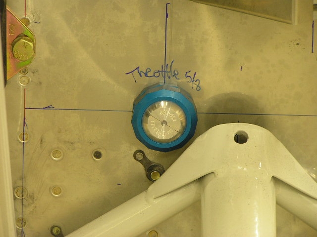 |
1.0 |
| 4/27/08 | I torqued the six bolts
attaching the engine mount to the firewall (160 in/lbs) and
installed the cotter keys.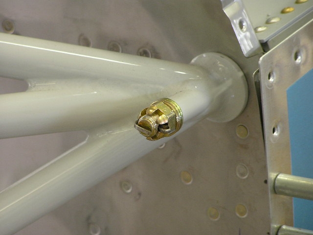 |
1.0 |
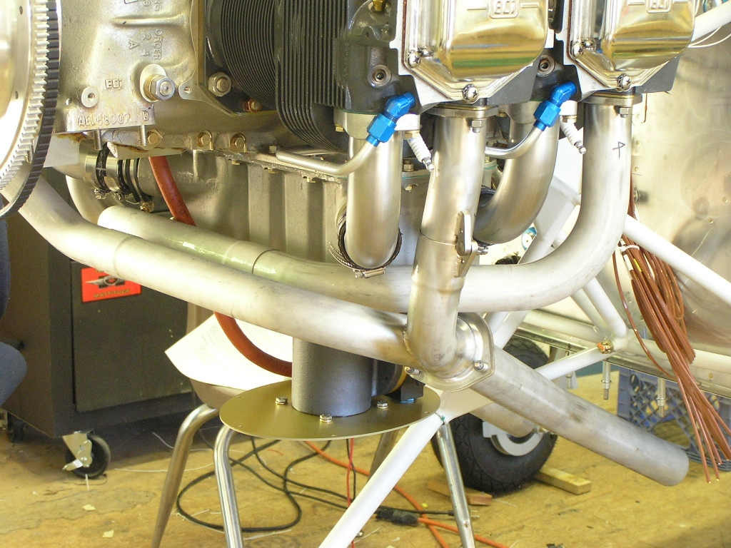
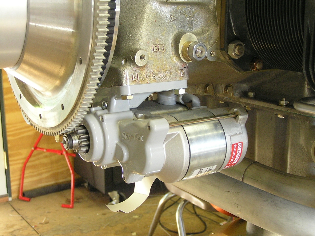
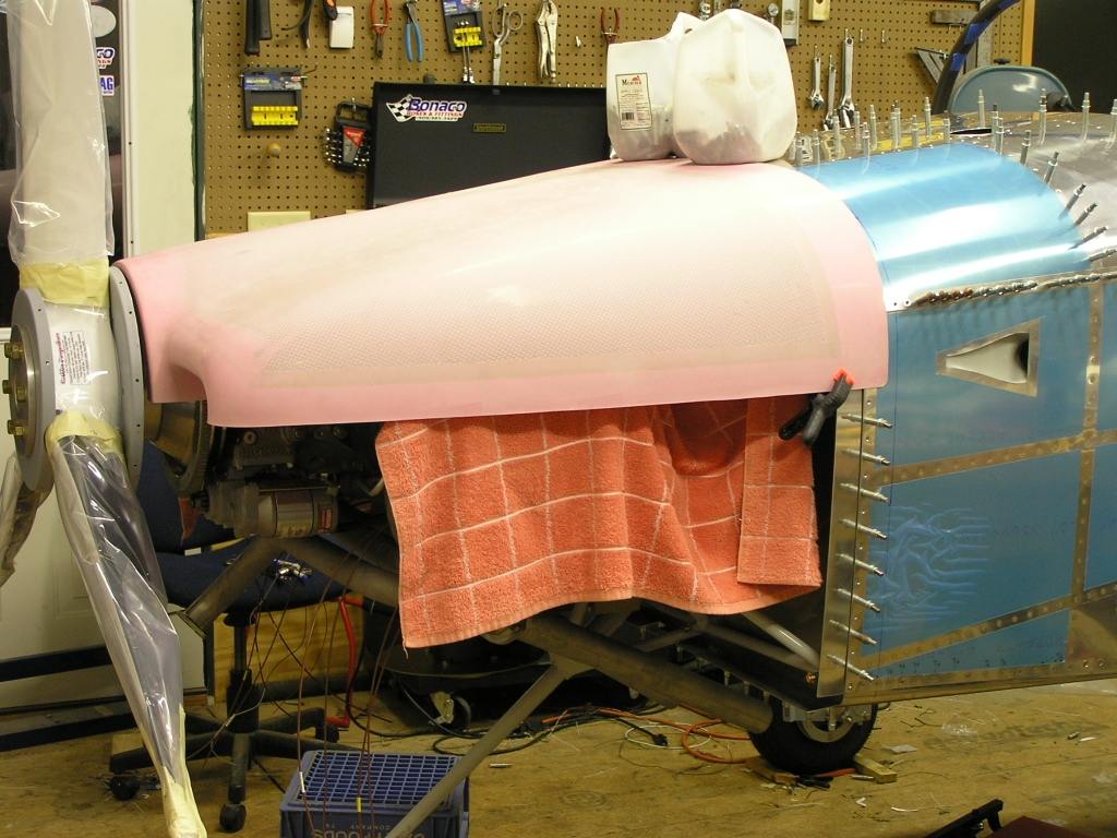
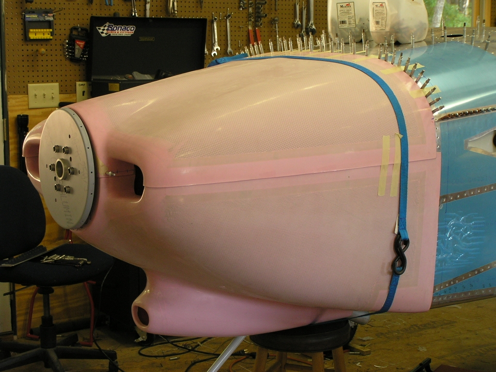
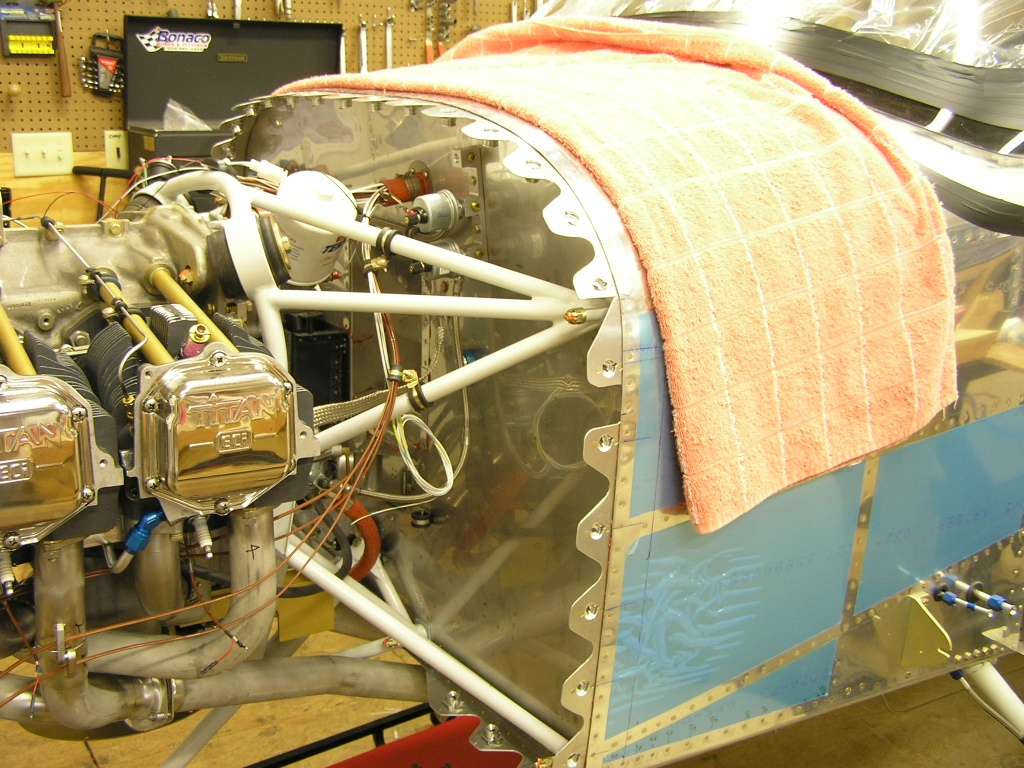
| 9/7/08 | I placed the top cowl on the engine just for
perspective...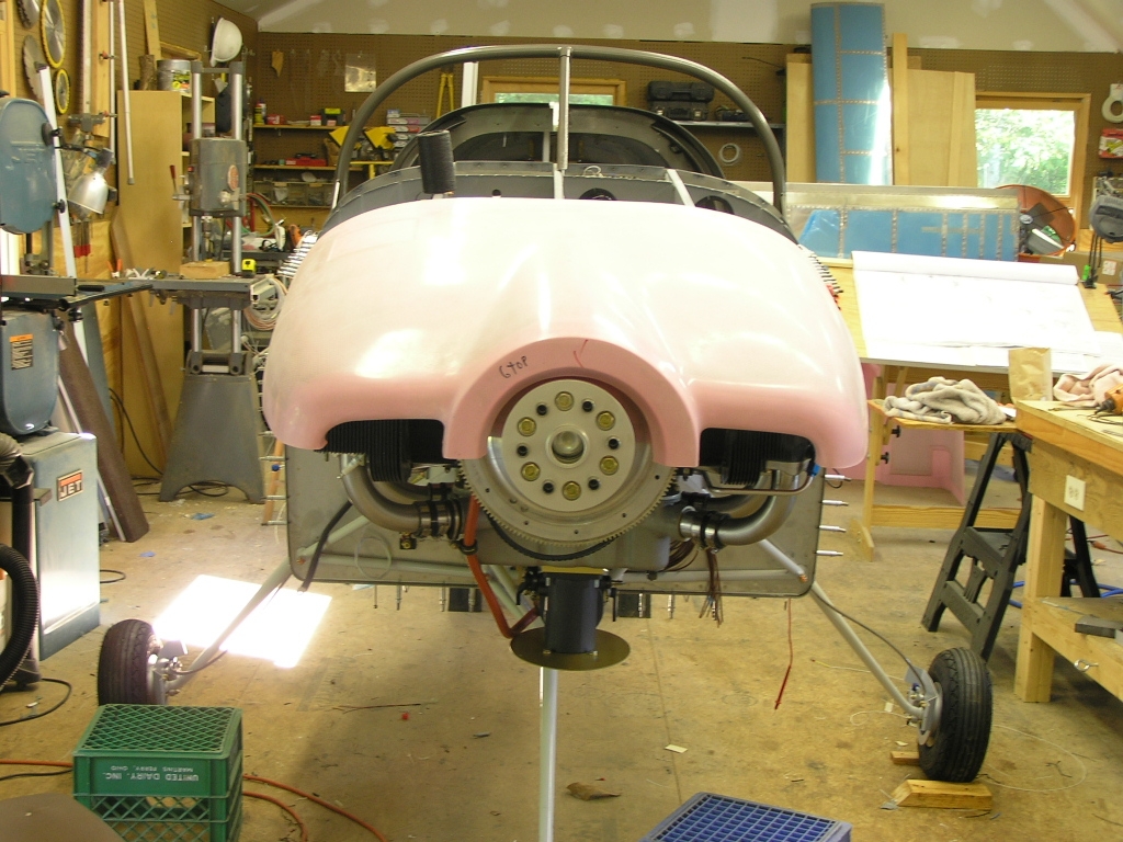
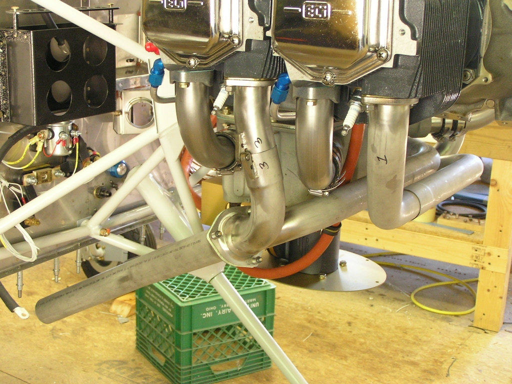
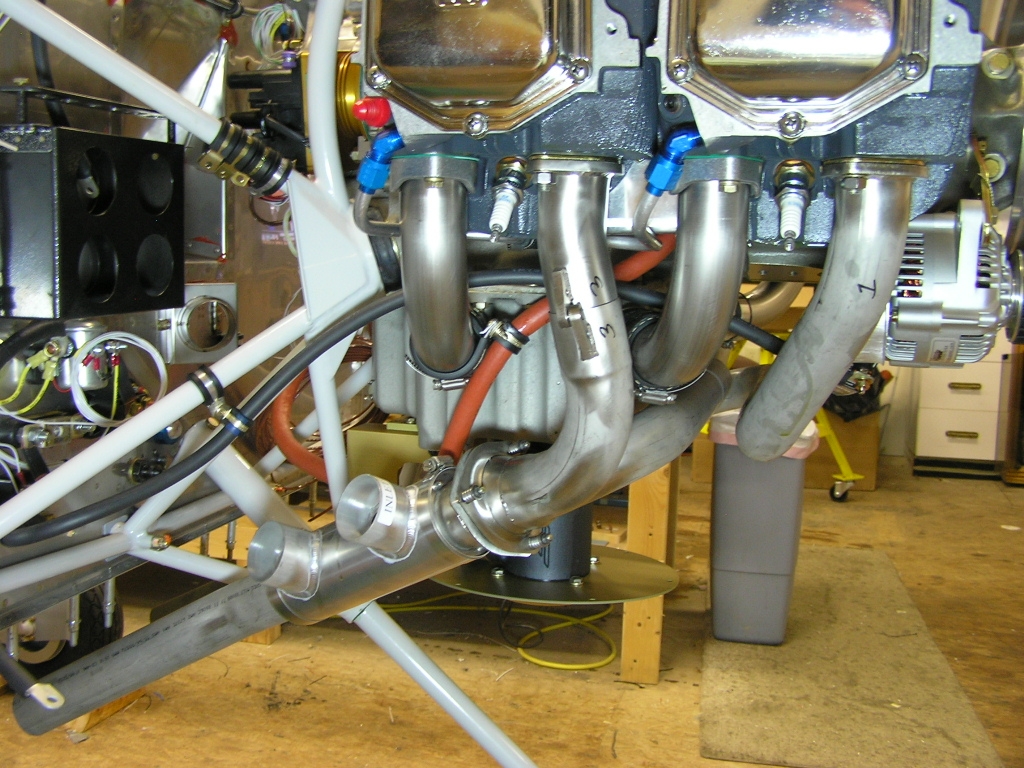
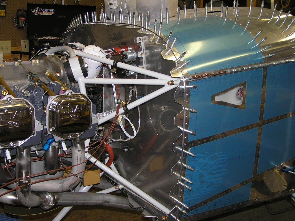
The Plans say the first thing to install is the exhaust as
everything else has to route around it. I bought the
system from Larry Vetterman at
Vetterman Exhaust. It was
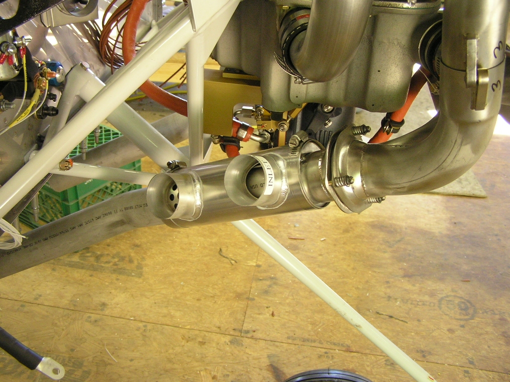
fairly easy to understand and went on in about an hour. I also installed the heat muff but will probably need to
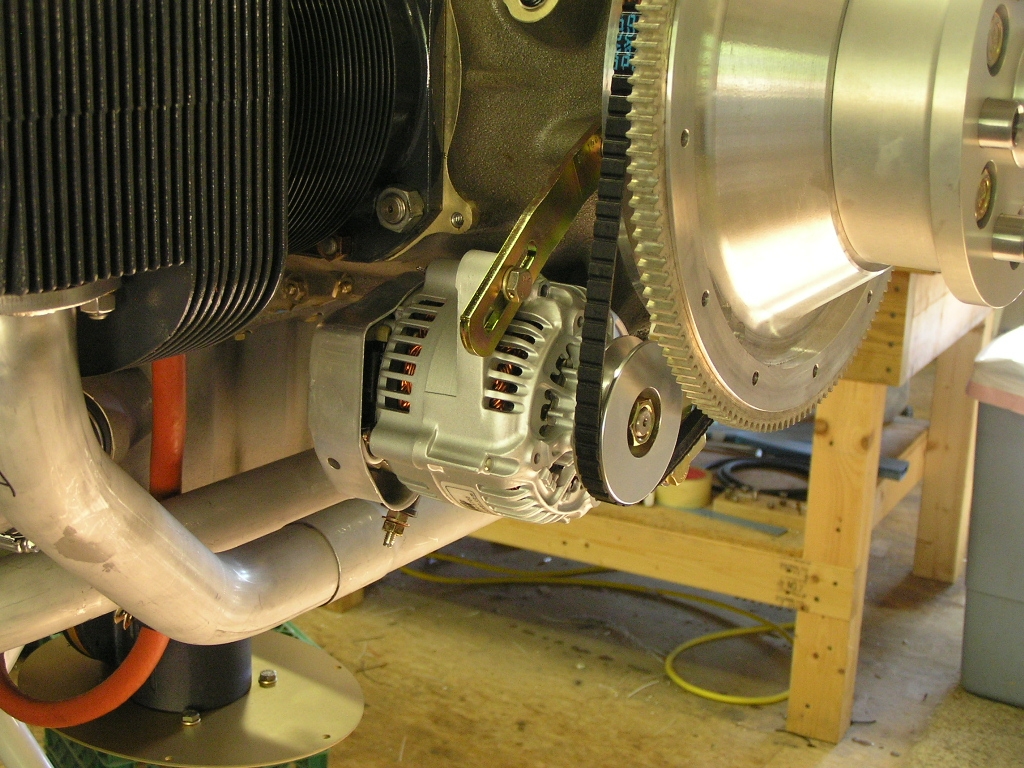
adjust it later. Next was the
Plane Power AL12-EI60/B
alternator. I just temporarily installed because I need to
confirm the torque value for the bracket bolts to the engine
case. I also need to purchase another belt so I can safety
tie it to the engine. This is a trick many builders use so
if a belt breaks they don't have to remove the prop to replace. Lastly, I installed the
Sky-Tec 149-12HT
starter. I torqued the bolts to 100 in/lbs. |
6.0
|
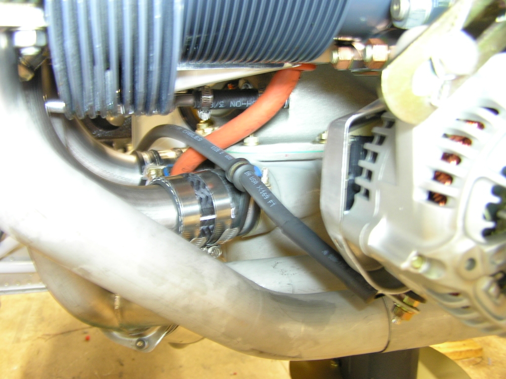
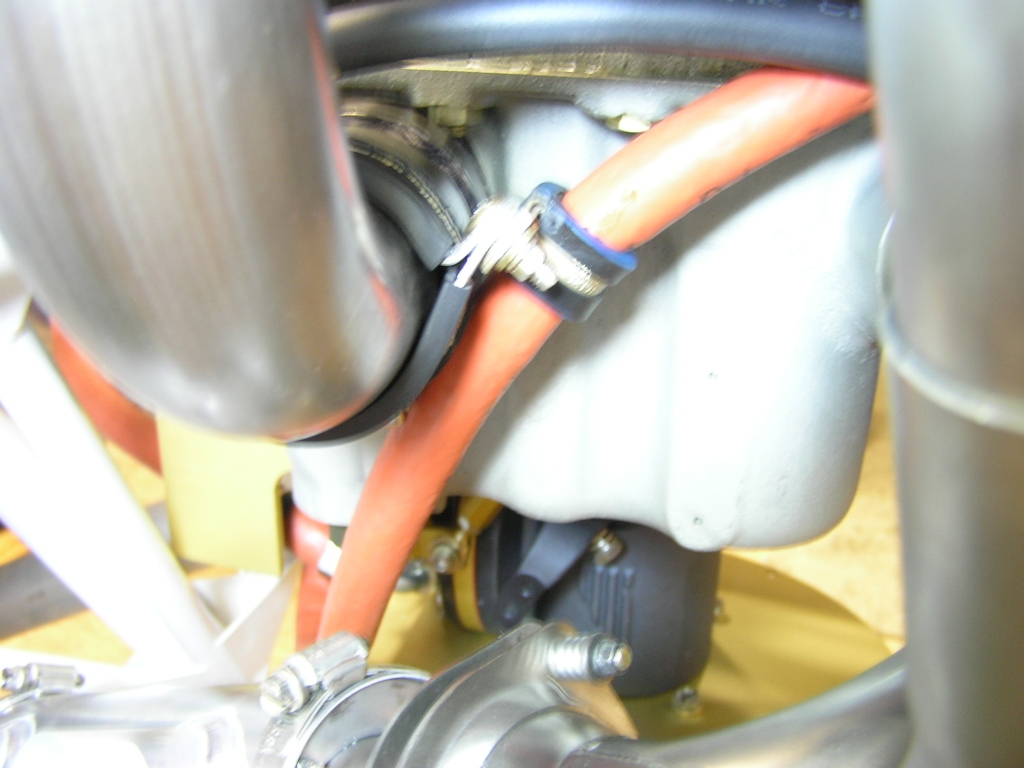
| 9/10/08 | Tonight I torqued the boss mount
for the alternator to 204 in/lbs and safety wired. I then
torqued the support arm and safety wired as well.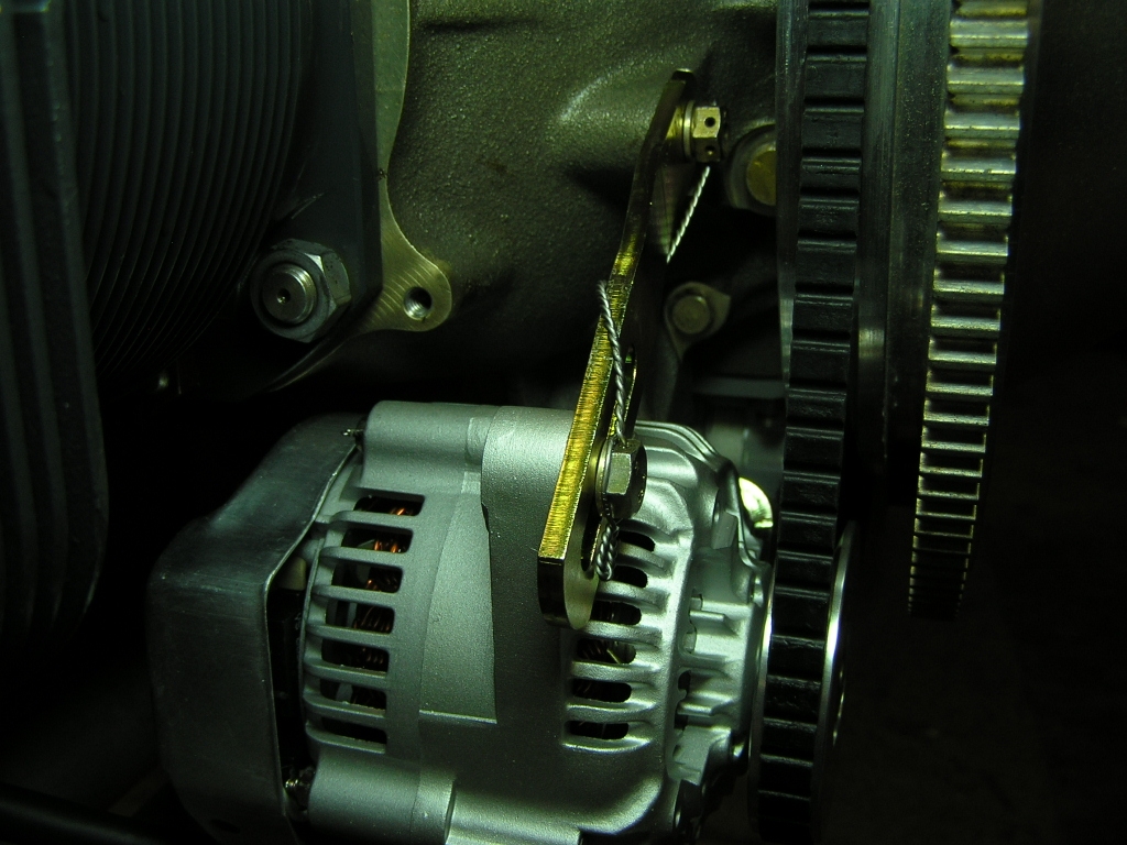
Next, I soldered connector lugs on a length of 2
AWG cable and connected the Alternator output terminal to the
shunt on the firewall. I also temporarily secured the
cable in two places with Adel clamps. I also secured the fuel line from the throttle
body to the servo where it runs up and through the
inner-cylinder baffle with a pair of Adel clamps. |
2.0 |
|
Prop Arrives! |
||
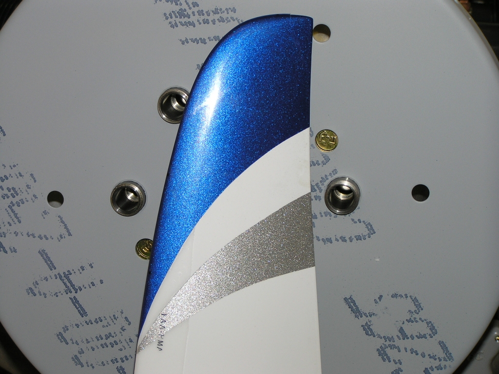
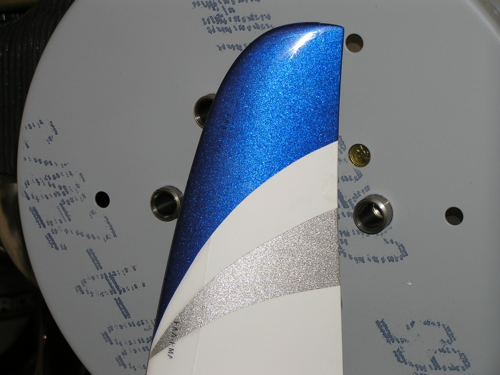
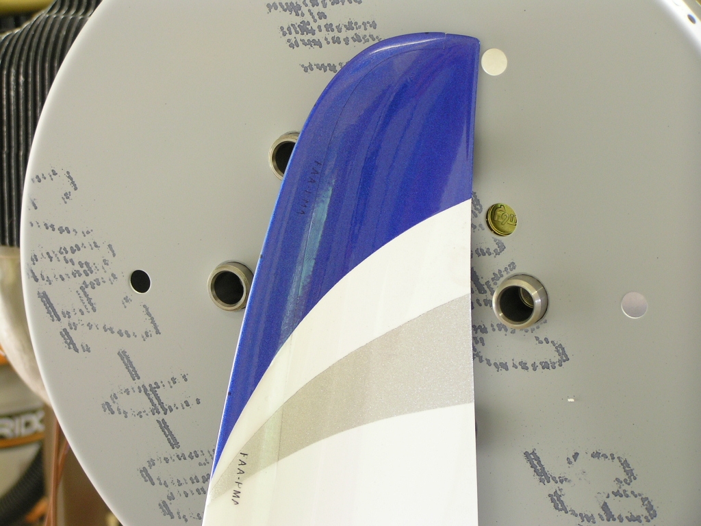
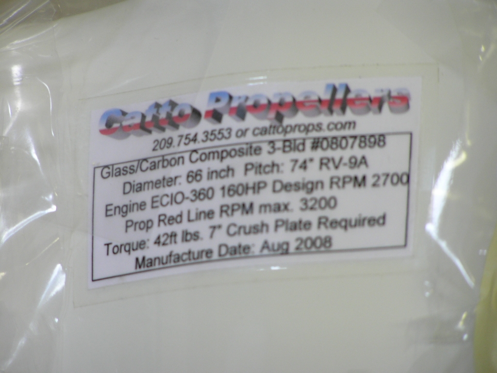
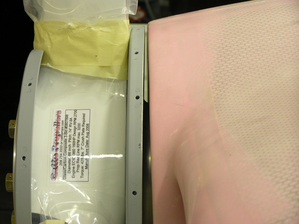
| 9/12/08 | I got an email Friday that my
Catto Prop had arrived at the Mineral Bluff Post Office so I
picked it up and brought it home. It was in excellent
condition and was packed very well.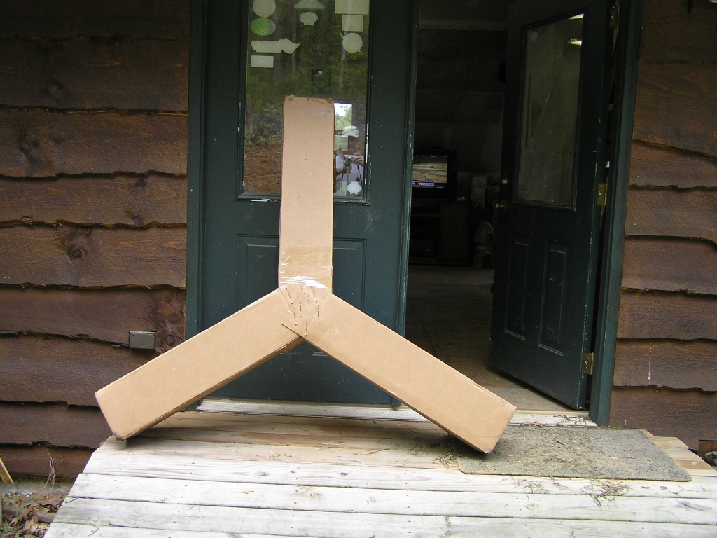 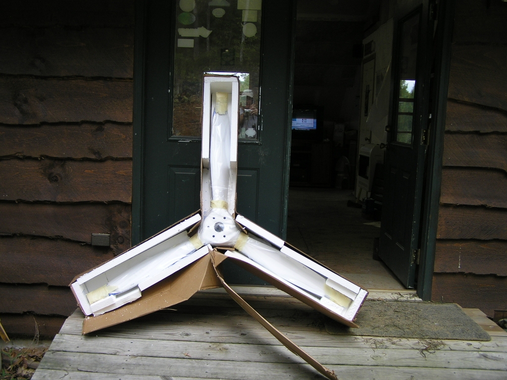 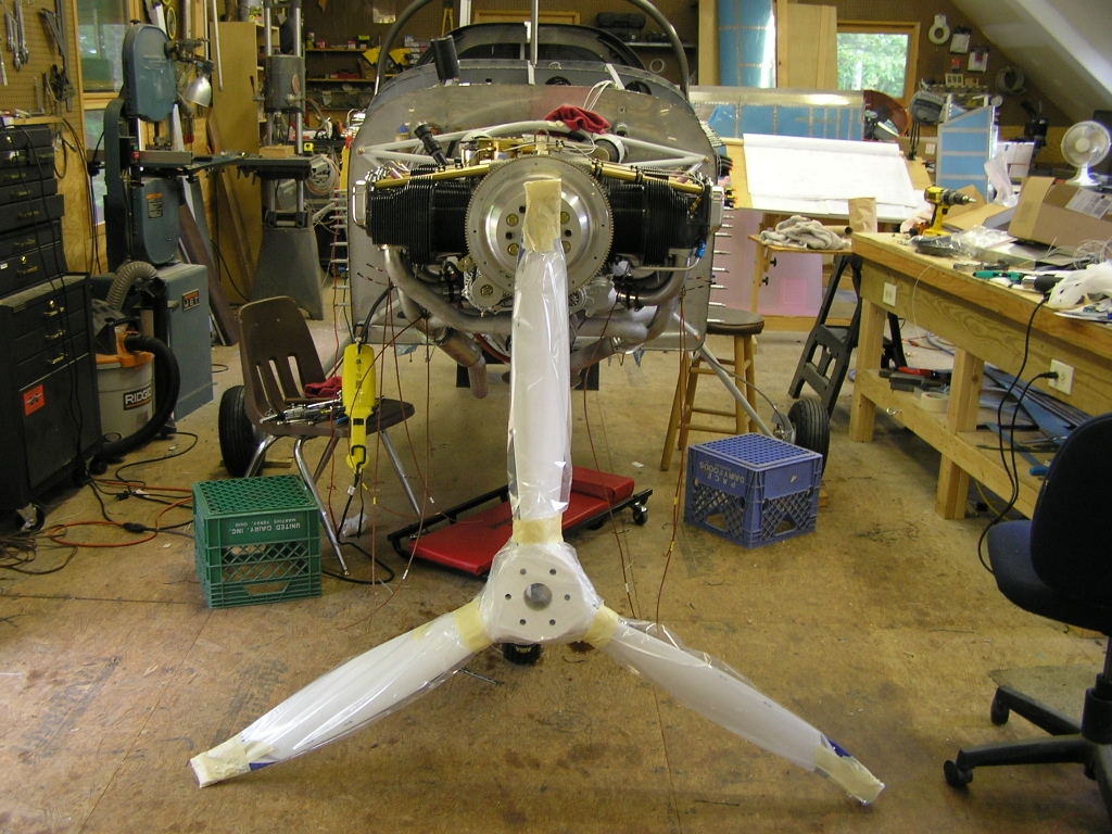
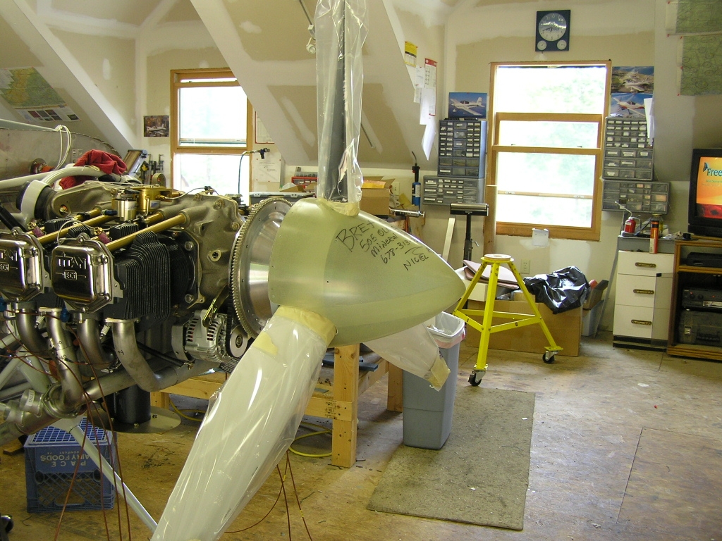
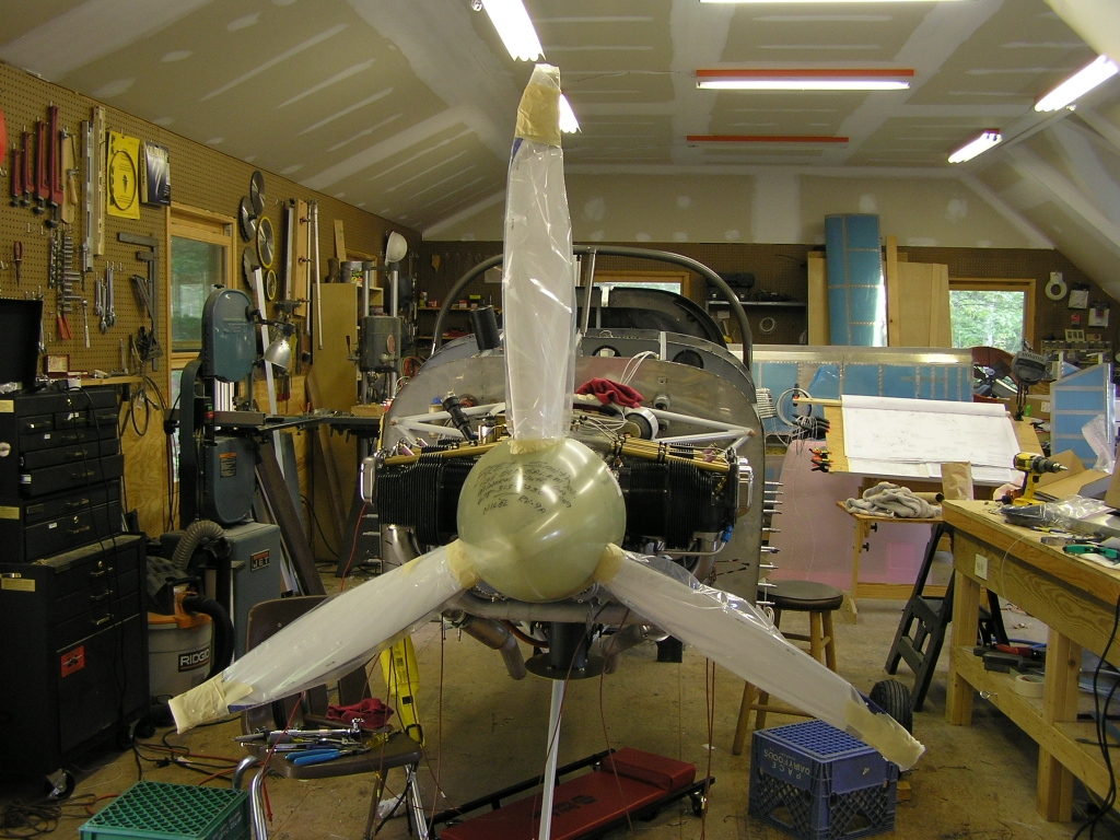
I took the tape and padding off one tip to
inspect the paint. I had shipped the paint to Craig having
never seen the true color (other than as painted on the
prototype HondaJet). The blue paint has a different look
when in different lighting conditions such as here when shot
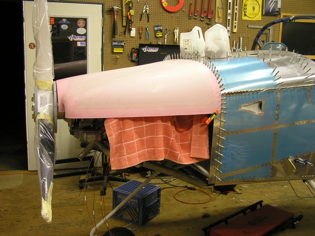
with flash and without. I took a picture of the prop label. I went ahead and temp-installed the prop and
test-fitted the spinner.
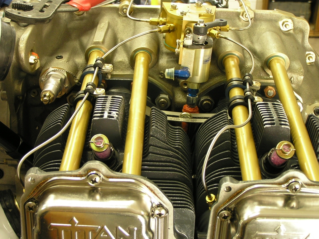
Installed Injector Fuel
Lines
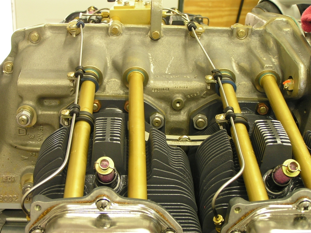
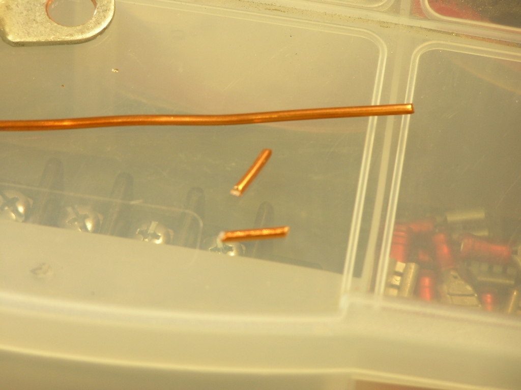
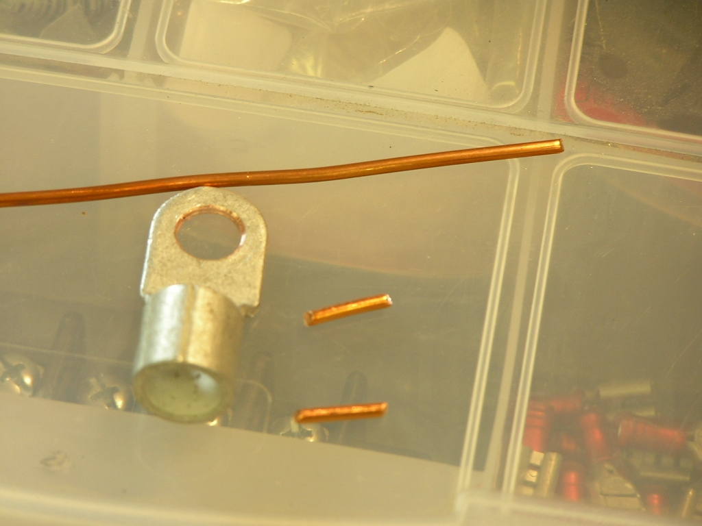
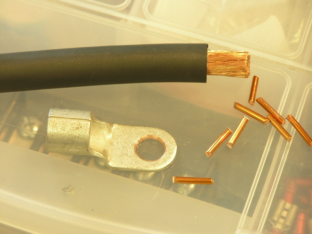
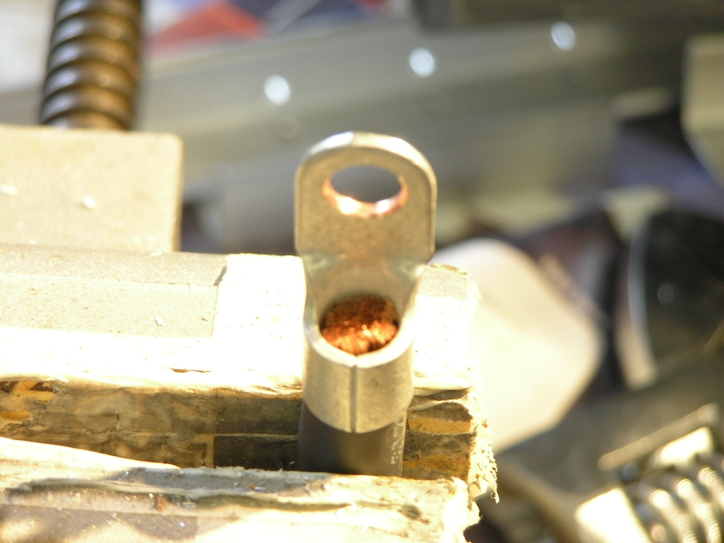
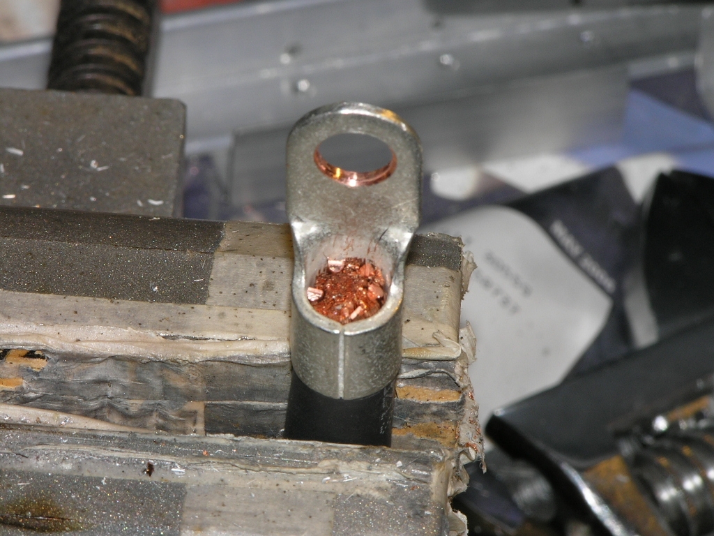
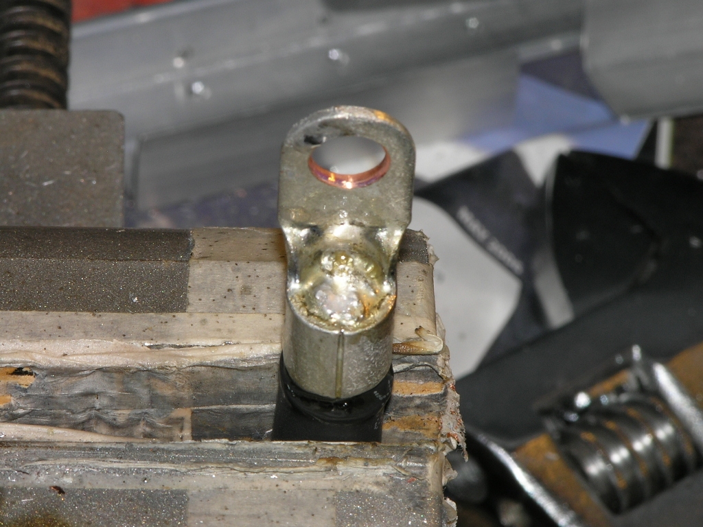
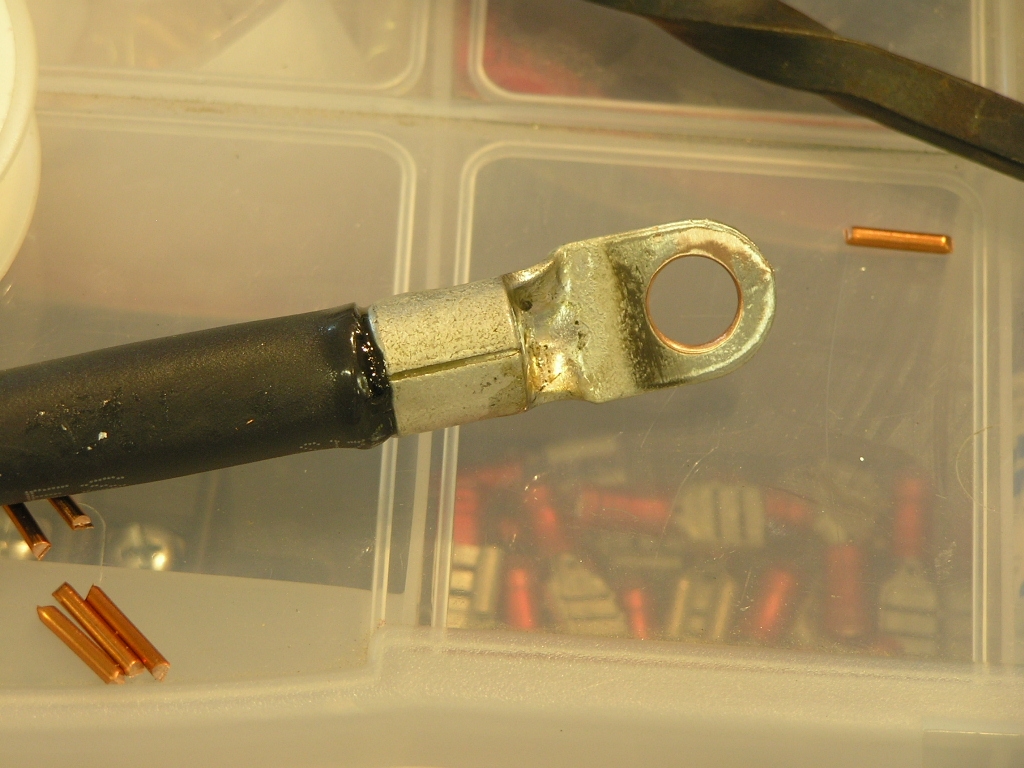
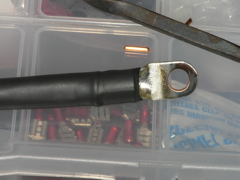
I wanted to show how to solder connectors on
the 2 AWG cable. These cables are used to connect the
alternator and starter as well as the main battery leads.
The only trick is to use a butane torch (Radio Shack) or a
propane torch on LOW flame to heat the connector and wire enough
for the solder to "wick" into the wire strands. The 14 AWG
wire pieces are used to fill the gaps and make a tight fit with
the wire and connector. I placed the cable in a vise to hold it steady
and used needle-nose pliers to insert the 14 AWG wire pieces. Add heat shrink and you are good to go! |
6.0 |
| 9/19/08 | Today I met
Bill Repucci who flew over from
Charlotte, NC to serve as a Tech Counselor visit. Bill
felt it was safe for me to keep building. We flew his RV-9
over to Blairsville airport for fuel and let me have a little
stick time. I wanted to get the top skin
on in order to fit the windscreen and begin fitting the cowl so
I concentrated on finishing lacing the wiring. I also ran
the alternator wiring to the panel. |
3.0 |
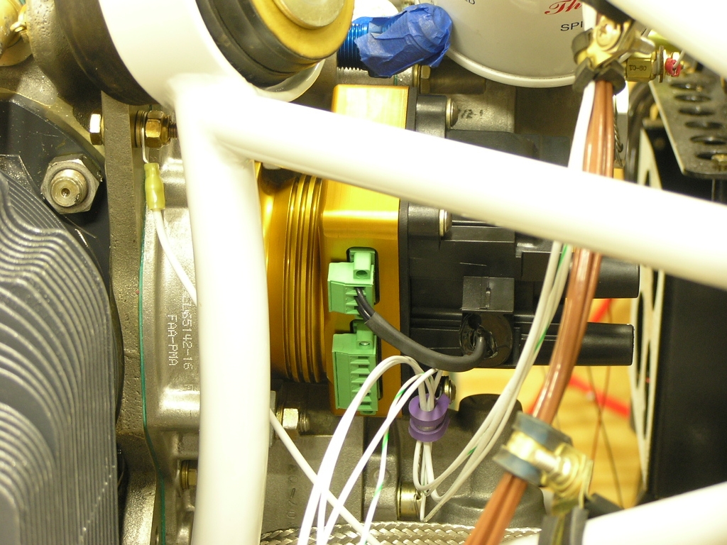
| 9/20/08 | I needed to arrange the wire
runs in the engine compartment so I decided to go ahead and
connect the fuel pressure transducer and the oil pressure
transducer. Added the fuel overflow fitting to the fuel
pump.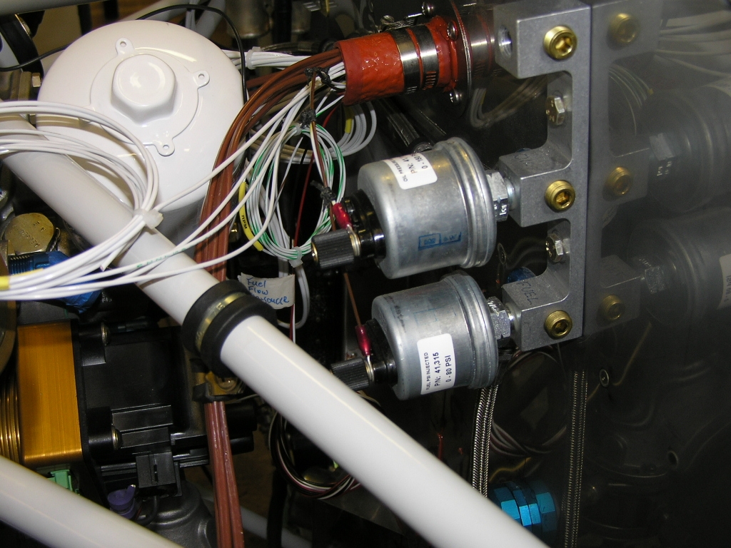 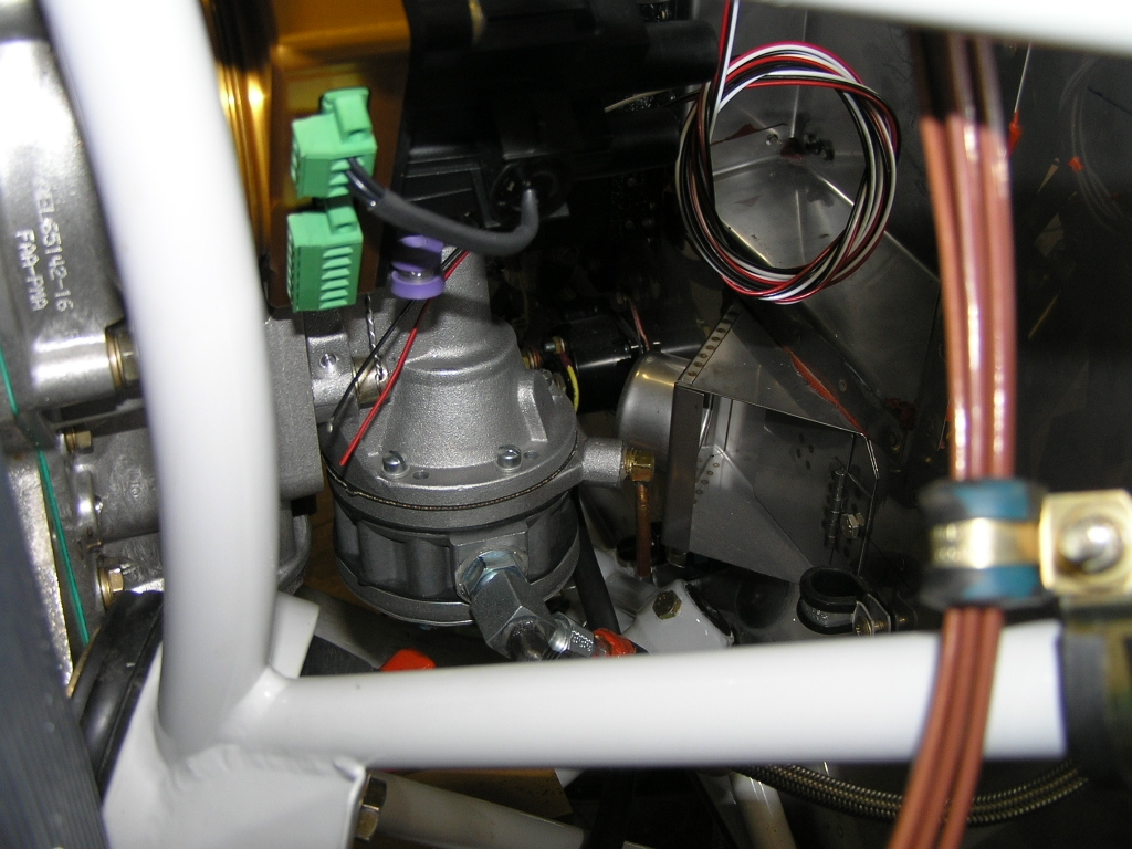 |
6.0 |
| 9/21/08 | Today I had lots of other
projects going so my plane time was minimal. I did go
ahead and pull my P-Mag and E-Mag for shipping back to Emagair
for compliance with the SB. I also went ahead and
installed the SD-8 backup alternator on the vacuum pump pad.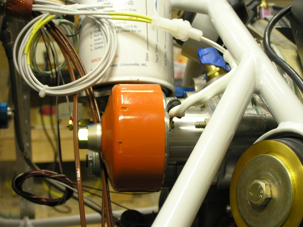
I spent most of my time working on
fitting the windscreen. |
4.0 |
|
Fitting the Cowling |
||
I spent about an hour trying to
get the cowl halves to fit together at the front. I tried
trimming and used a file to clean up the mold lines but there is
only so much I can do. I will be trying to get the prop
opening as close to round as possible and then work to get the
top cowl mounted.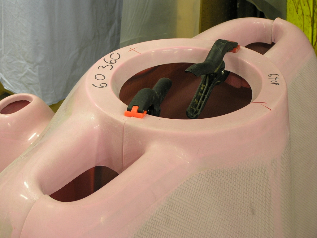 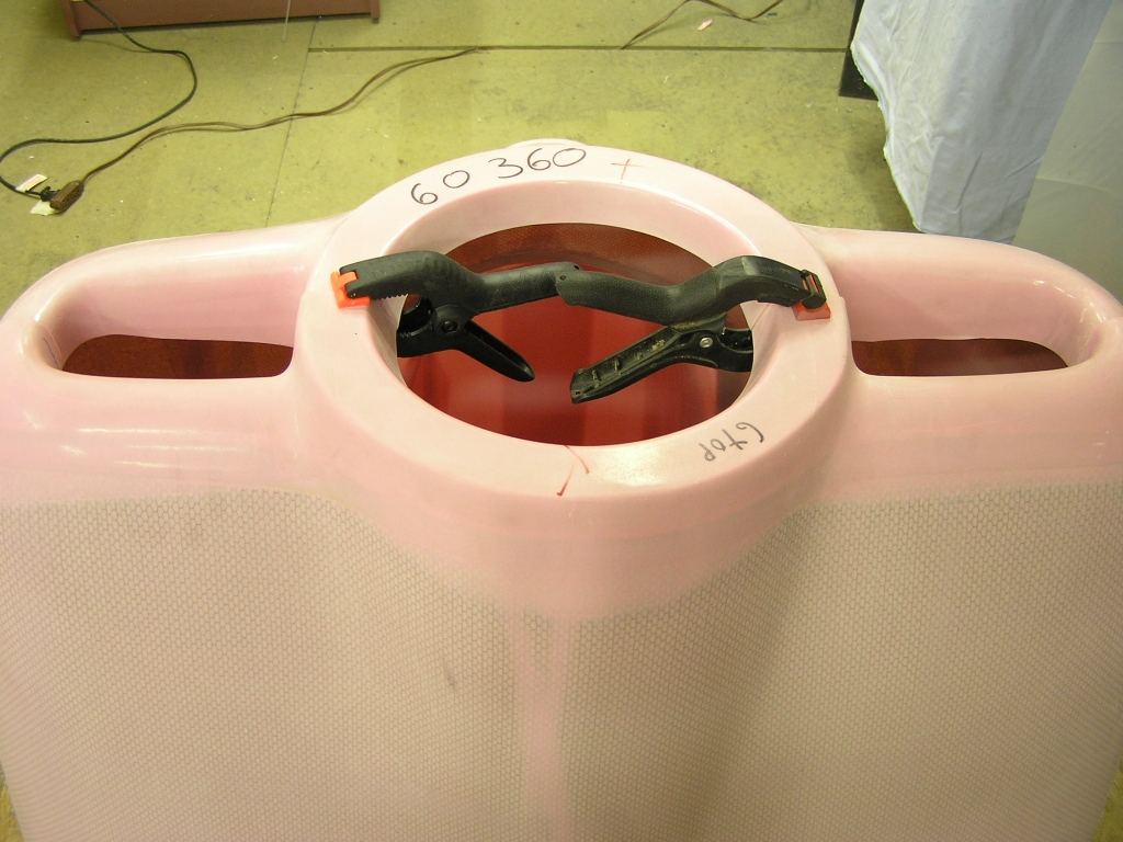 |
||
|
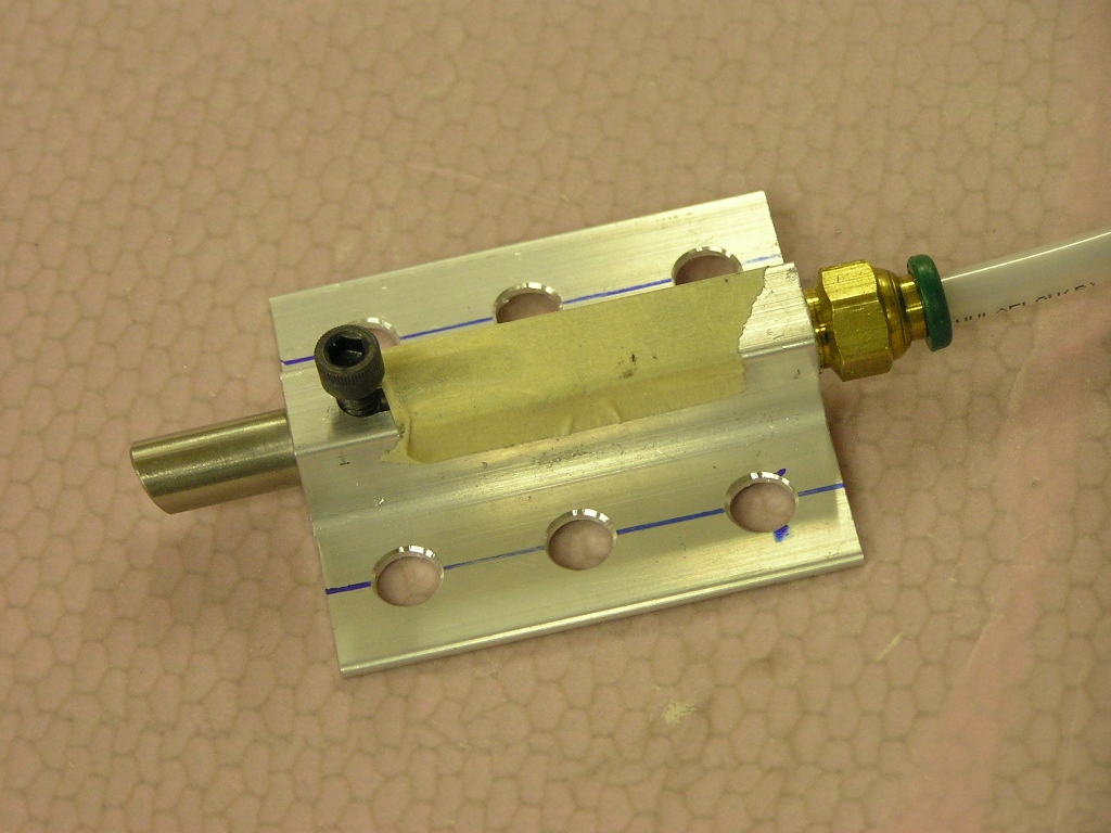
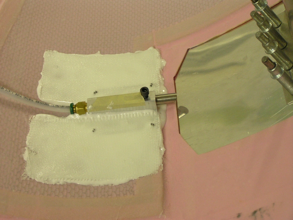
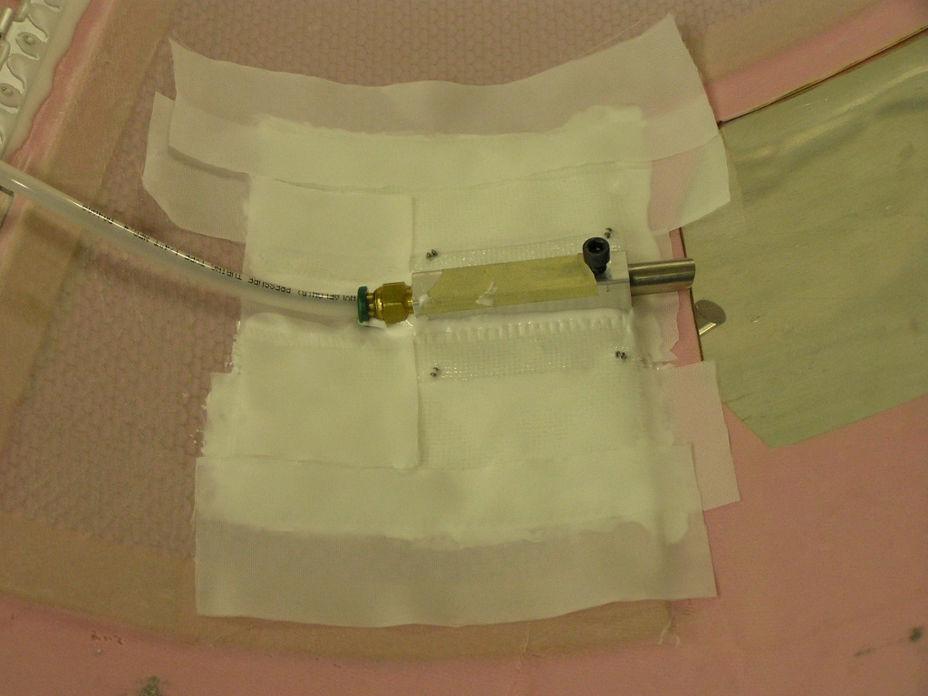
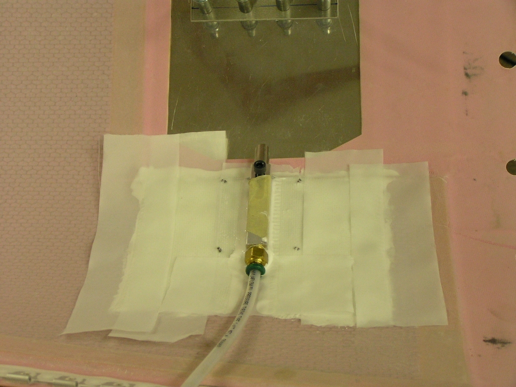
Fuel Flow Transducer |
||
| 9/26/08 | I installed the AFS fuel flow
transducer temporarily in order to see how it will work. I
can see no reason why it won't so I ordered custom hoses from
Brett at Bonaco to replace the
stock fuel hose I got with the Airflow Performance fuel
injection system.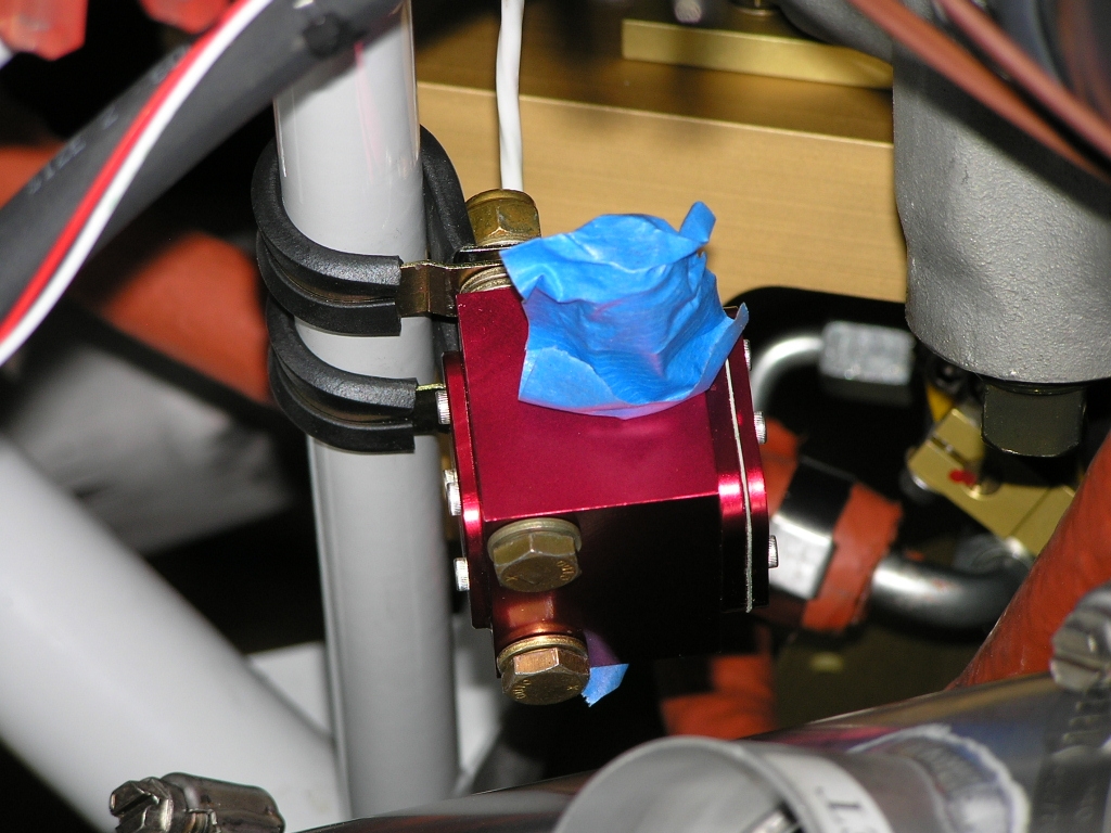 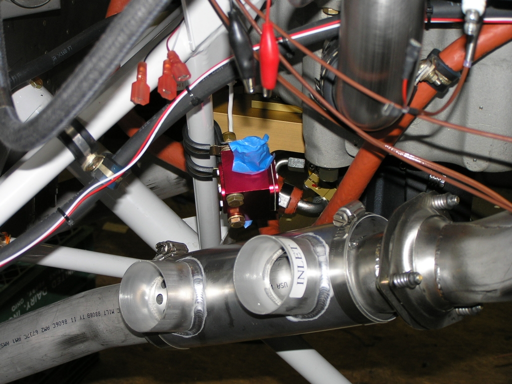 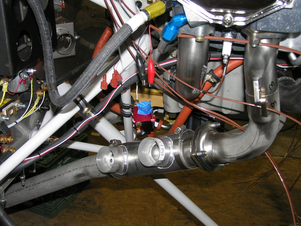
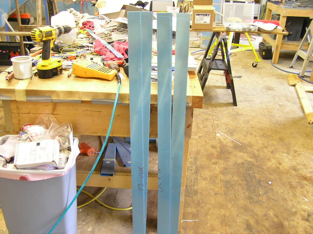
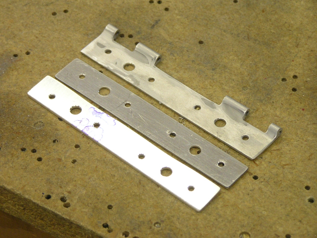
I stopped by a local sheet metal shop today and
had them cut strips 2.25" from a sheet of .064". These
will be the support strips for the Skybolt
cowl fasteners. |
2.0 |
| 9/27/08 | Installed the two
braided grounding straps I got from B&C.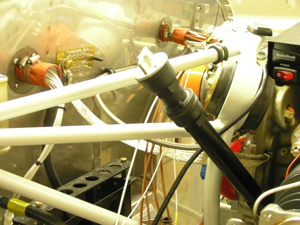 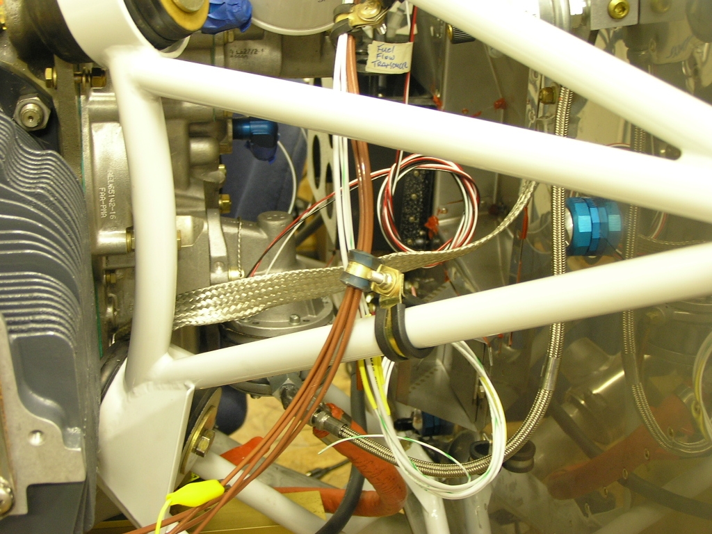
I then drilled the strips to the firewall
flanges. I made one solid piece for the top, two for the
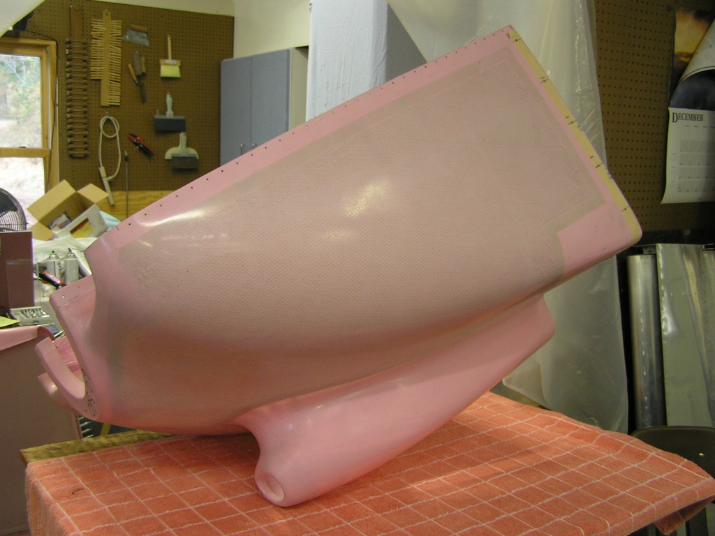
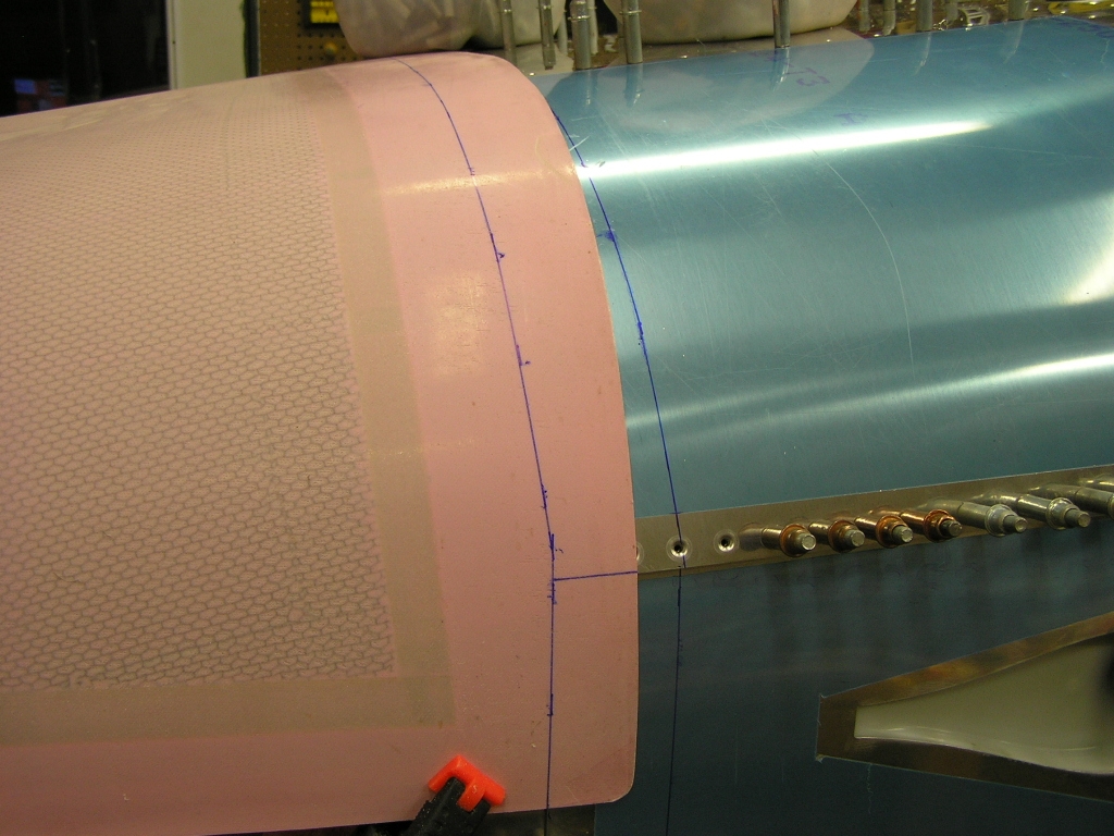
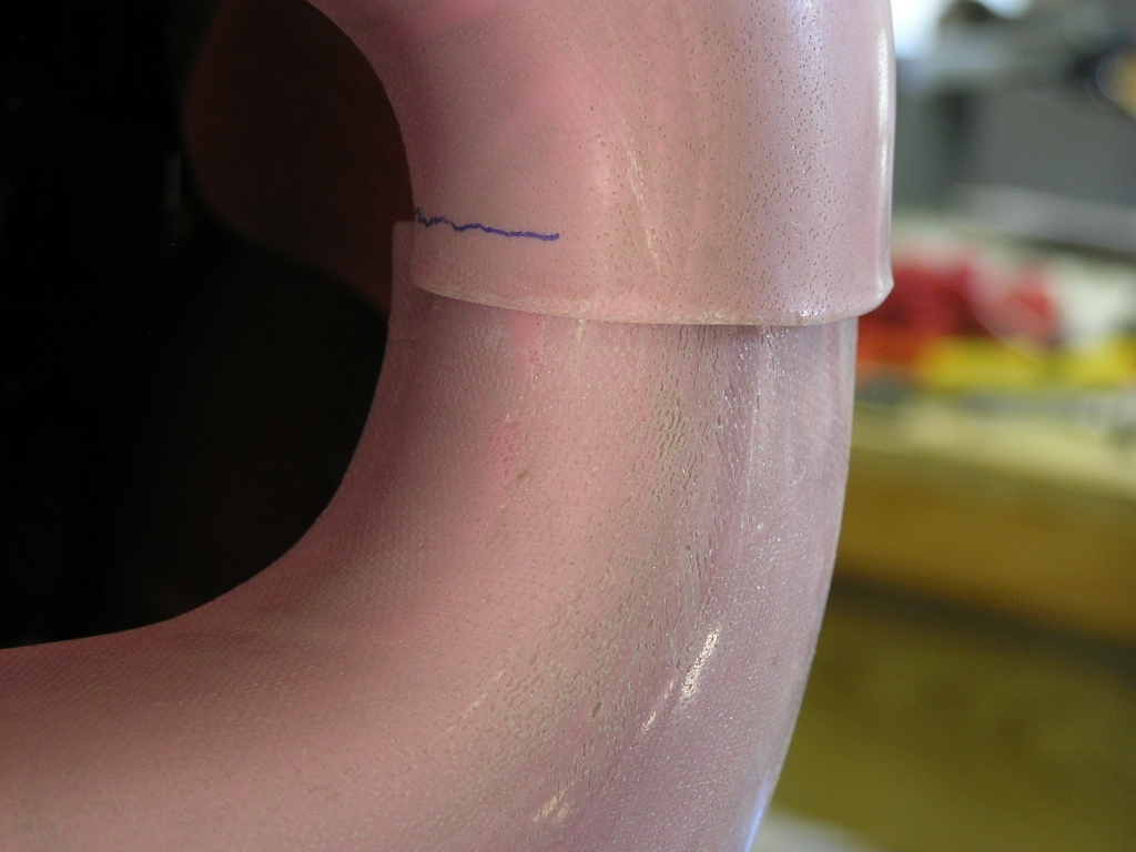
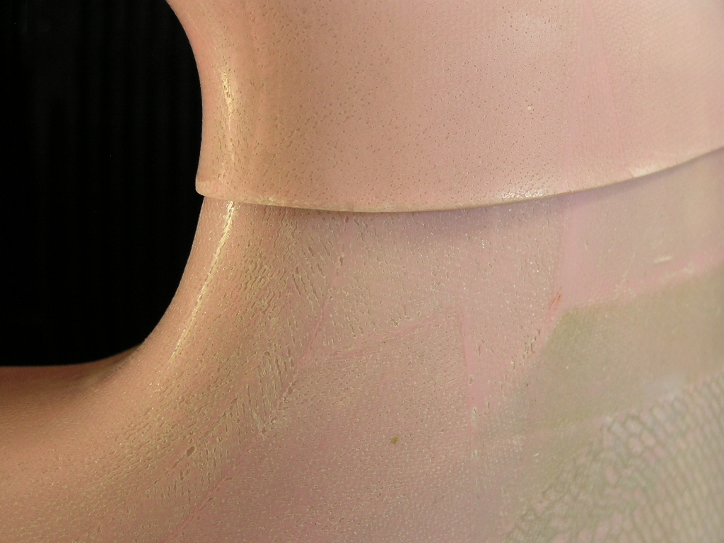
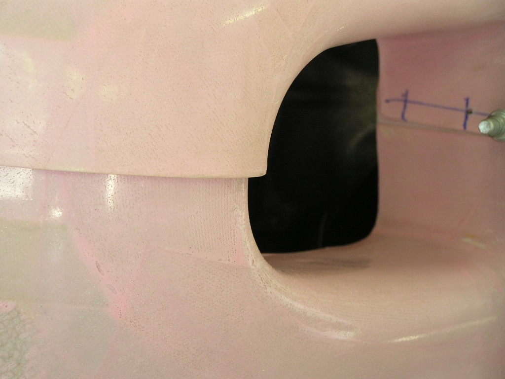
sides and two for the bottom. I cut the strips 2.5". I started fitting the top cowl by scribing a
line 2.0" behind the firewall flange. I then marked back
on the cowl and cut with my Dremel tool. I made sure to
leave a 1/8" gap between the spinner back-plate and the cowl. |
6.0 |
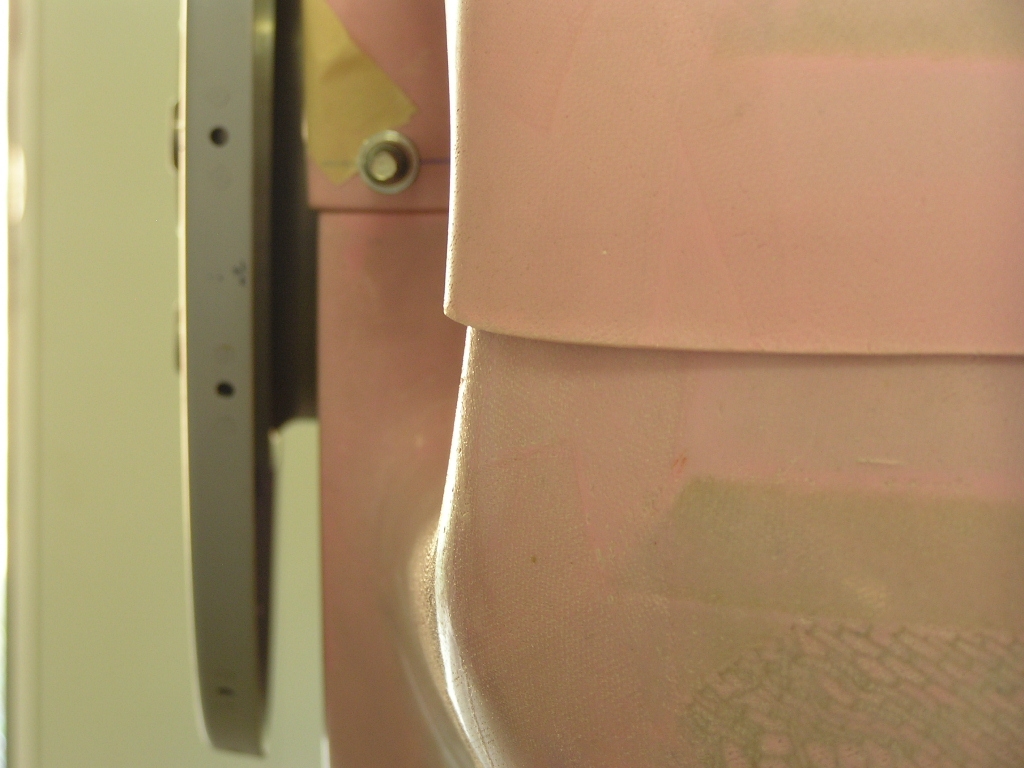
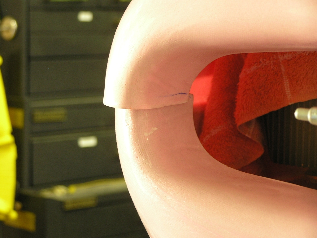
| 9/28/08 | After getting the top cowl
close, I started trimming the bottom cowl by cutting out the gap
for the nose gear. Since I have a Catto three-blade prop,
I had to extend the cut an additional 3.0".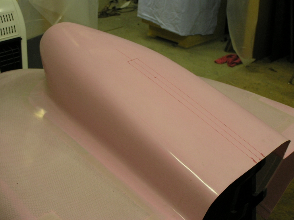
I finally was able to get the bottom cowl in
place but I am not pleased with the fit of the cowl halves at
the front. I will be researching how others dealt with the
poor fit before continuing. Here is the left side... Here is the right side. |
4.0 |
| 10/9/08 | I spent several hours last
weekend as well as a few nights this week trimming and fitting
the cowl halves. I would cleco the halves in place and
mark where it needed trimming then re-cleco them back up.
After way too much time, I had them fitting well enough to drill
the side hinges.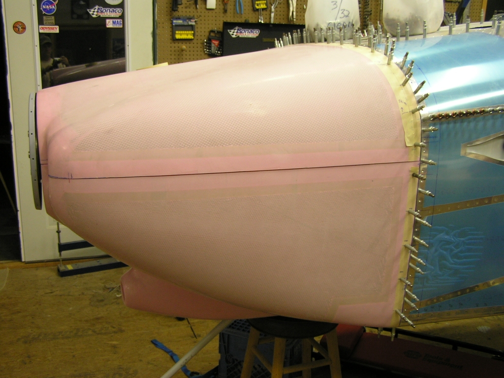 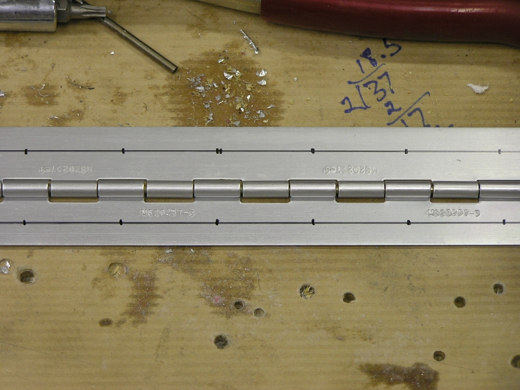 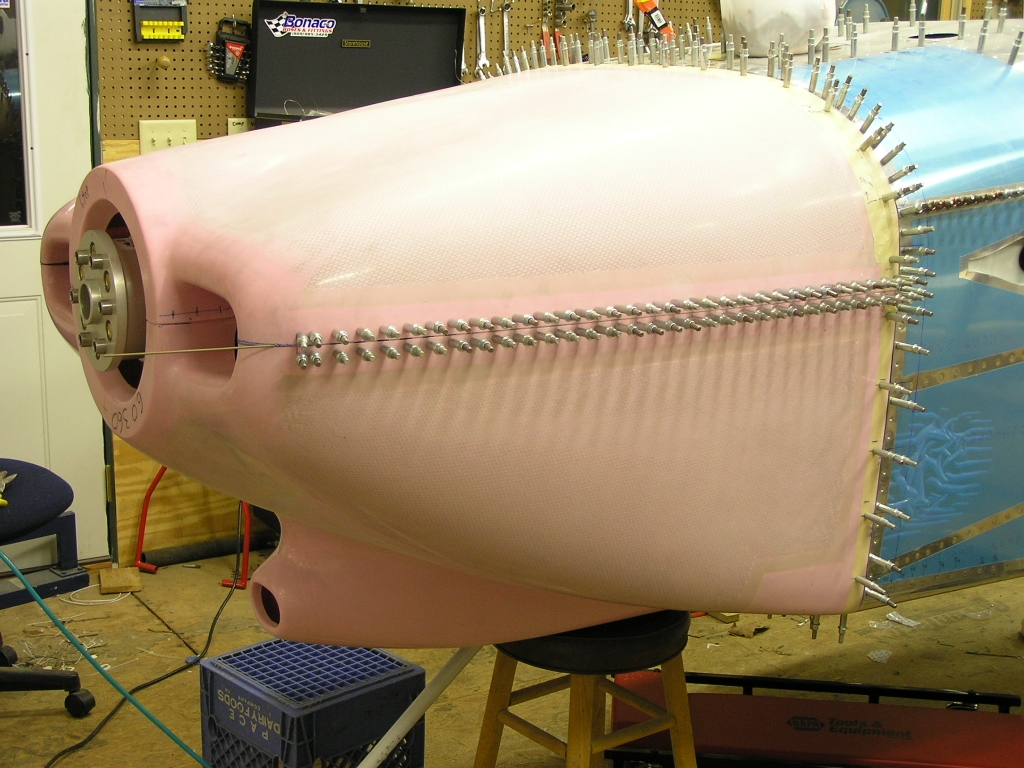 |
12.0 |
|
Installing Mounting Strips |
||
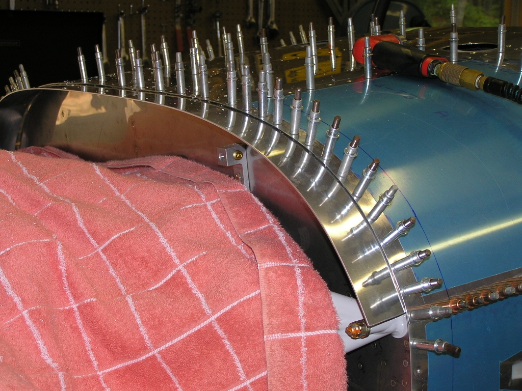
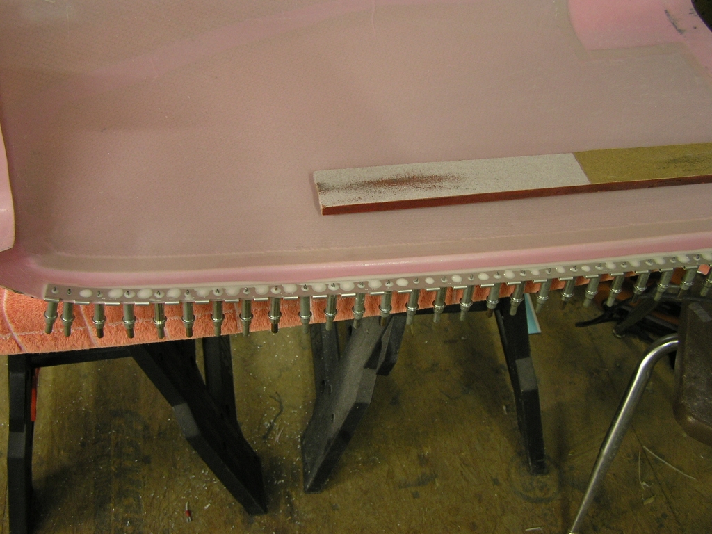
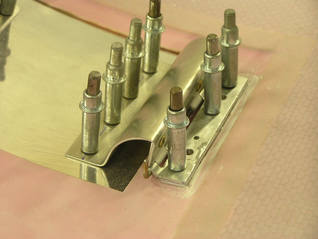
| 10/10/08 | I laid out the
spacing for the Skybolt fasteners around the firewall and
trimmed them to final size. Skybolt suggests a spacing
between fasteners of 3.5"-4.0" but I have seen some cowls that
"pucker" between the fasteners in flight. I set my spacing
at 3.25" across the top and 3.5" on the sides and bottom.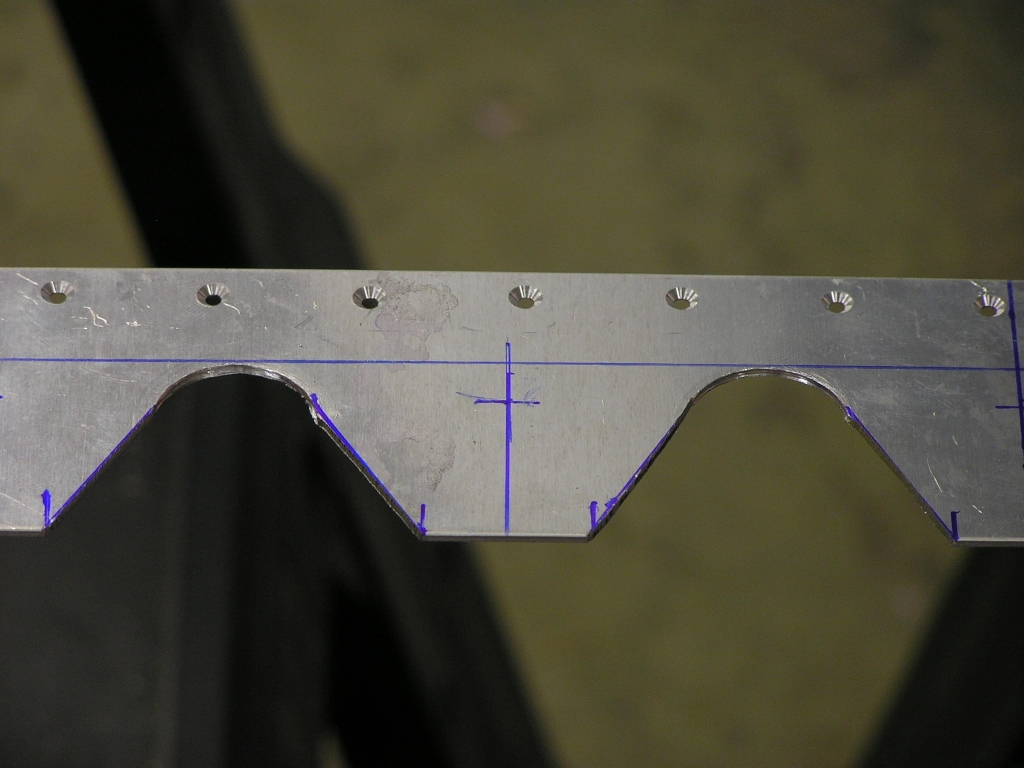
I then installed the cowl halves and drilled #40
to mark the fastener location. |
6.0 |
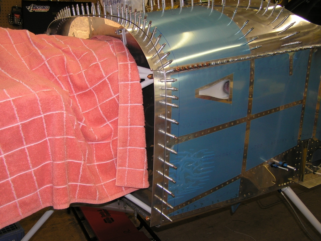
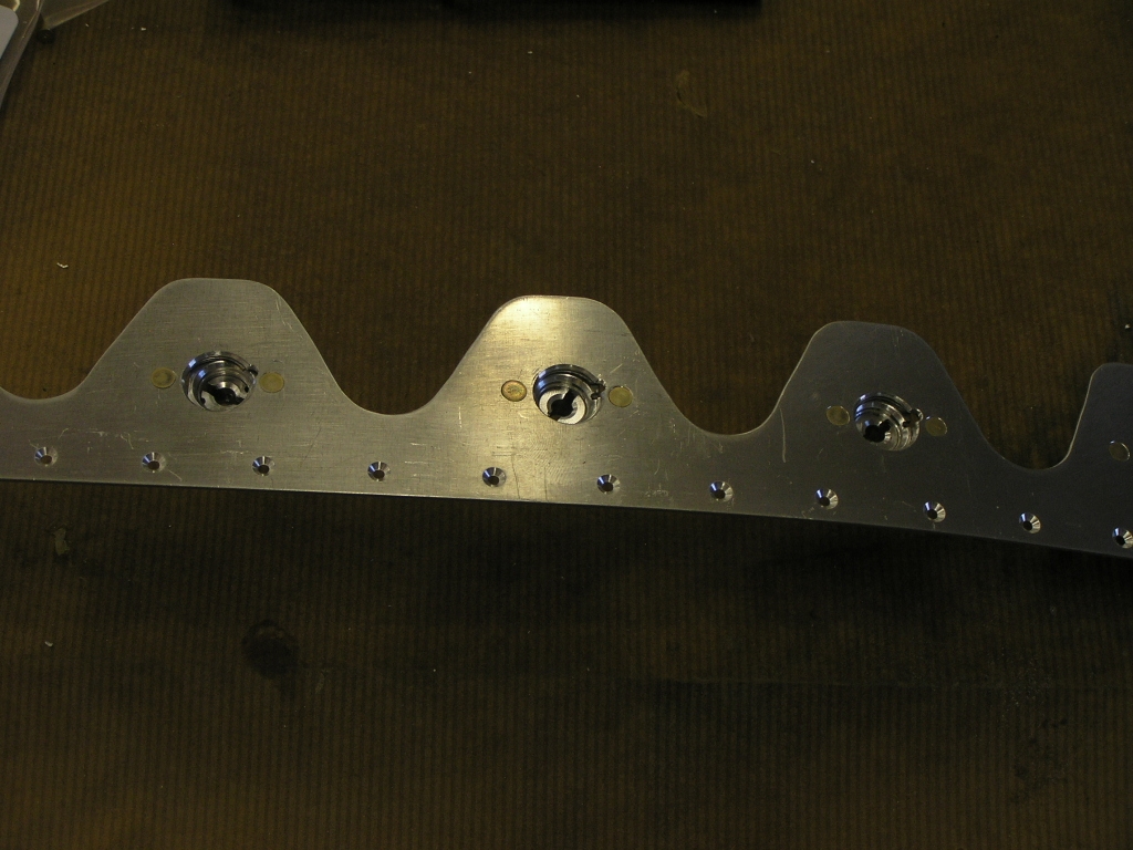
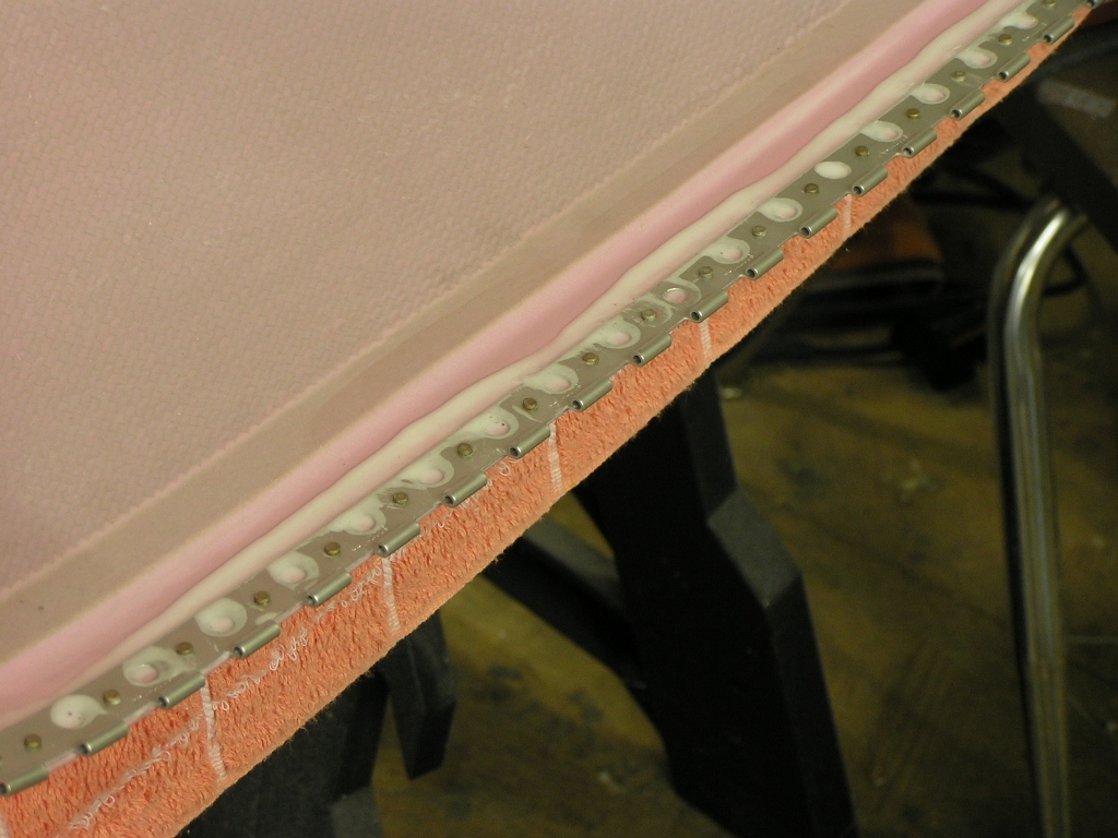
| 10/11/08 | Today I used the drill template
and drilled each fastener to #30 in order to rivet the fasteners
to the strips. 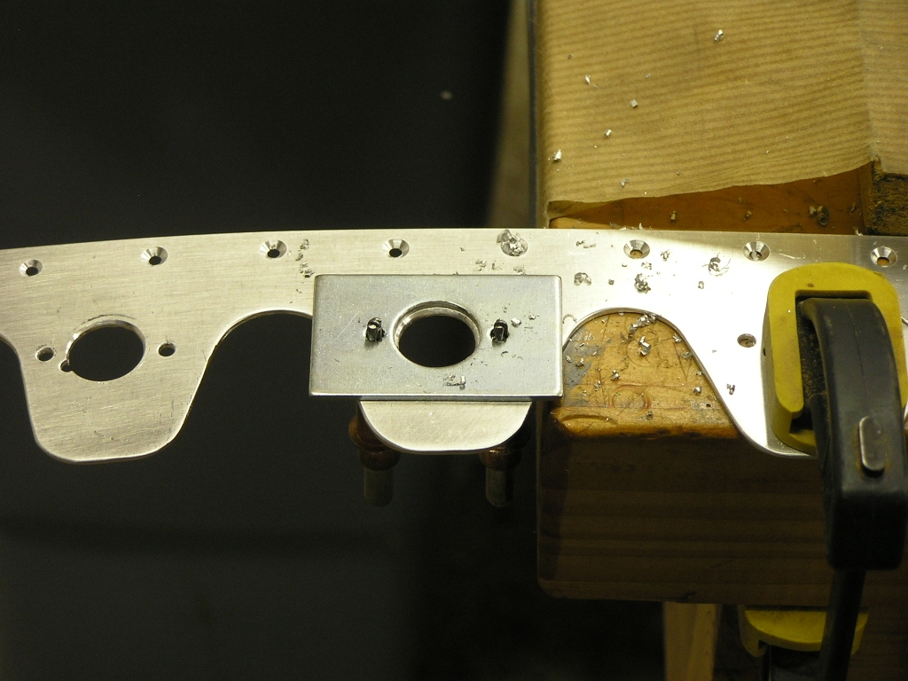
Next, you use another template and drill the
center hole to 11/32" using a #3 Unibit. Then you rivet
the 33 fasteners to the strips (making sure to align the
fasteners with the adjustment hole). Lastly, I riveted the fastener strips to the
firewall flange. |
6.0 |
|
Installing Cowl Hinges |
||
| 10/17/08 | I prepped the side hinges for
the lower cowl for riveting by drilling 1/4" holes between the
rivets for the epoxy to help adhere to the hinge. I then
countersunk the rivet holes along the side of the lower cowl.
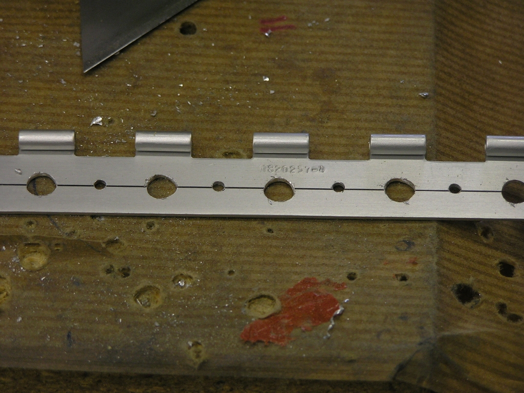 
I then mixed up some epoxy with micro balloons to
thicken it up and applied a thick layer to the cowl. I
then laid the hinge section in and clecoed every hole.
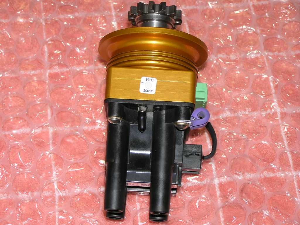
After letting it set up for an hour, I riveted. While waiting for the epoxy to set up, I went
ahead and re-installed my P and E-Mags. I had removed them
a couple of weeks ago and shipped them back to
Emagair due to a SB. They installed a neat temperature
strip on the Mags to alert me if the mags ever are getting too
hot. |
3.0 |
| 10/18/08 | I epoxied and riveted the right
side hinge on the bottom cowl.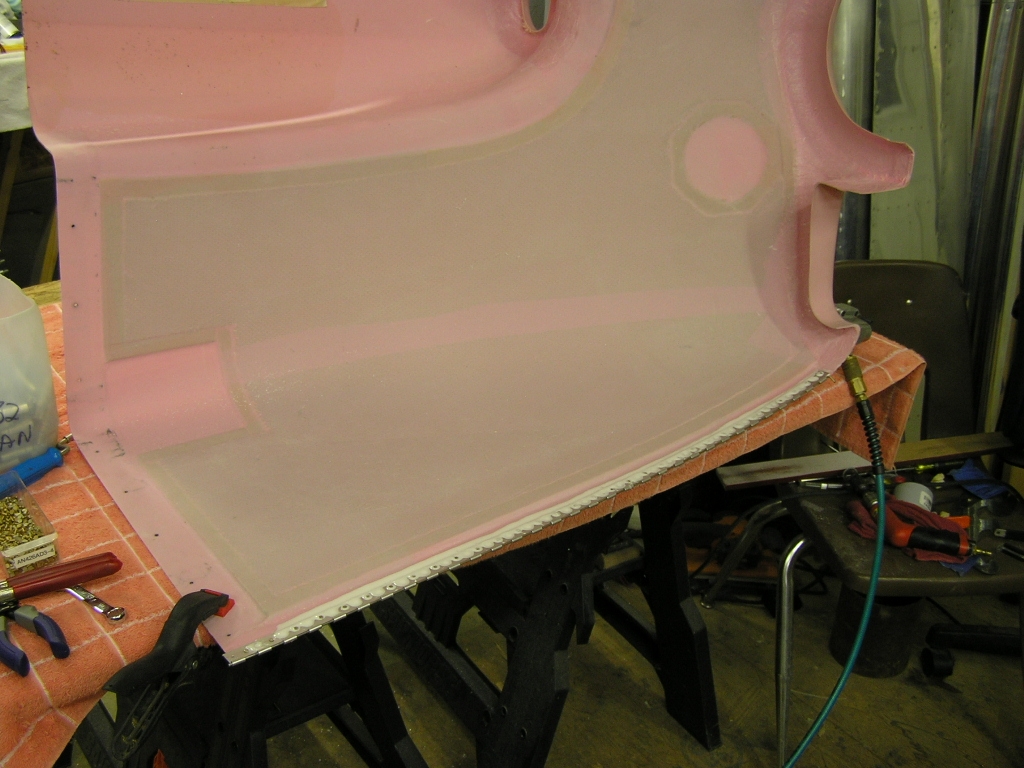 |
2.0 |
| 10/19/08 | Today I mixed a batch of 50%
epoxy/50% acetone and brushed on to the bottom cowl and set
aside to cure. Afterwards, I will sand it down and repeat
in order to get a handle on the pinholes. I also epoxied
and riveted the right side hinge on the top cowl. |
2.5 |
| 10/20/08 | Epoxied and riveted the right
side hinge on the top cowl.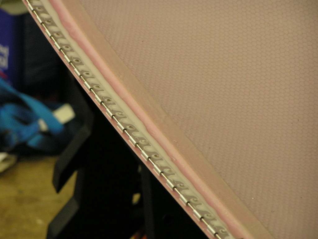 |
2.0 |
|
Pinhole Removal |
||
| 10/21/08 | This evening I mixed a batch of
50% epoxy/50% acetone and brushed on to the top cowl.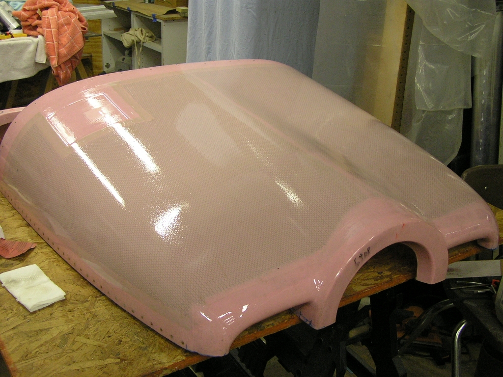 |
.5 |
| 11/1/08 | I washed both cowl halves with dishwashing
liquid and rinsed with water. After drying, I sanded the
top and bottom cowl halves and blew all the sanding dust off.
I will be using the Loehle WonderFil
for pinhole removal and then spraying with a sanding sealer.
This will suffice until I get around to painting the plane. 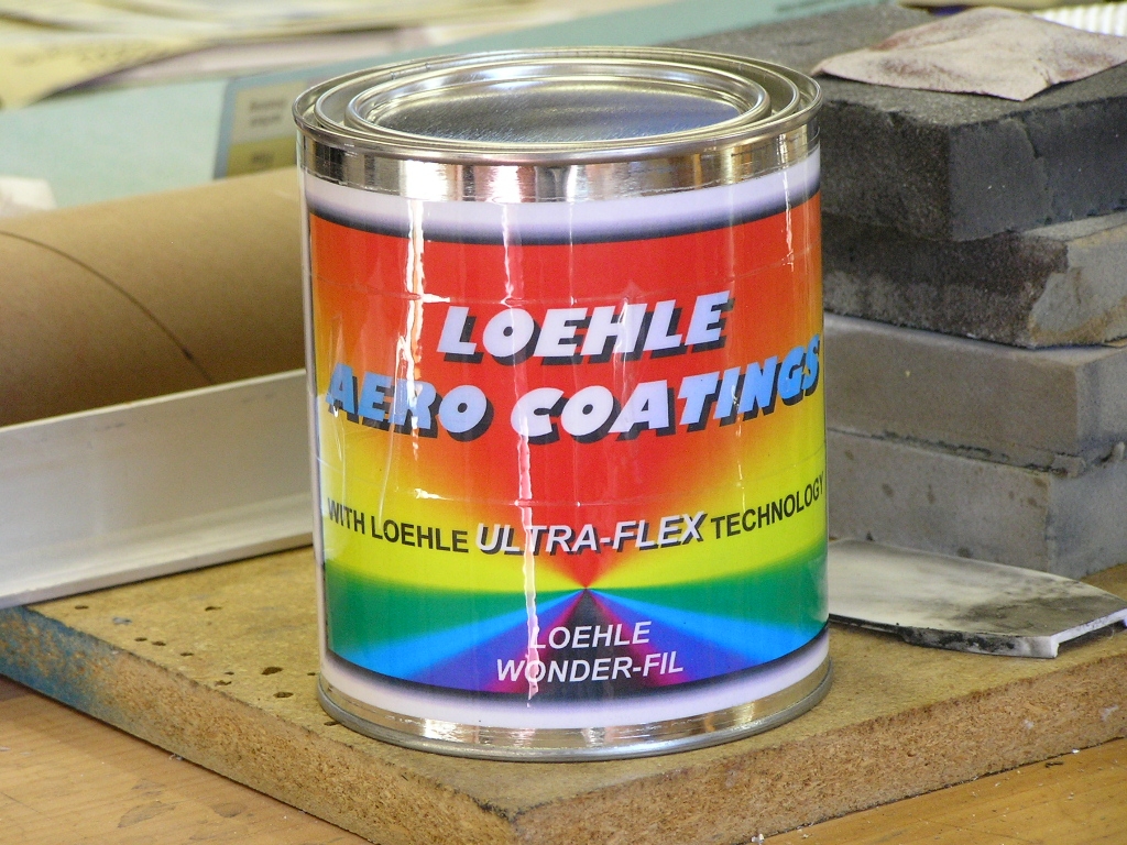 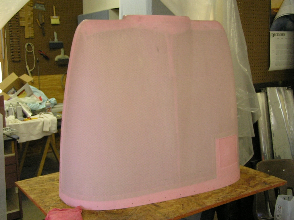 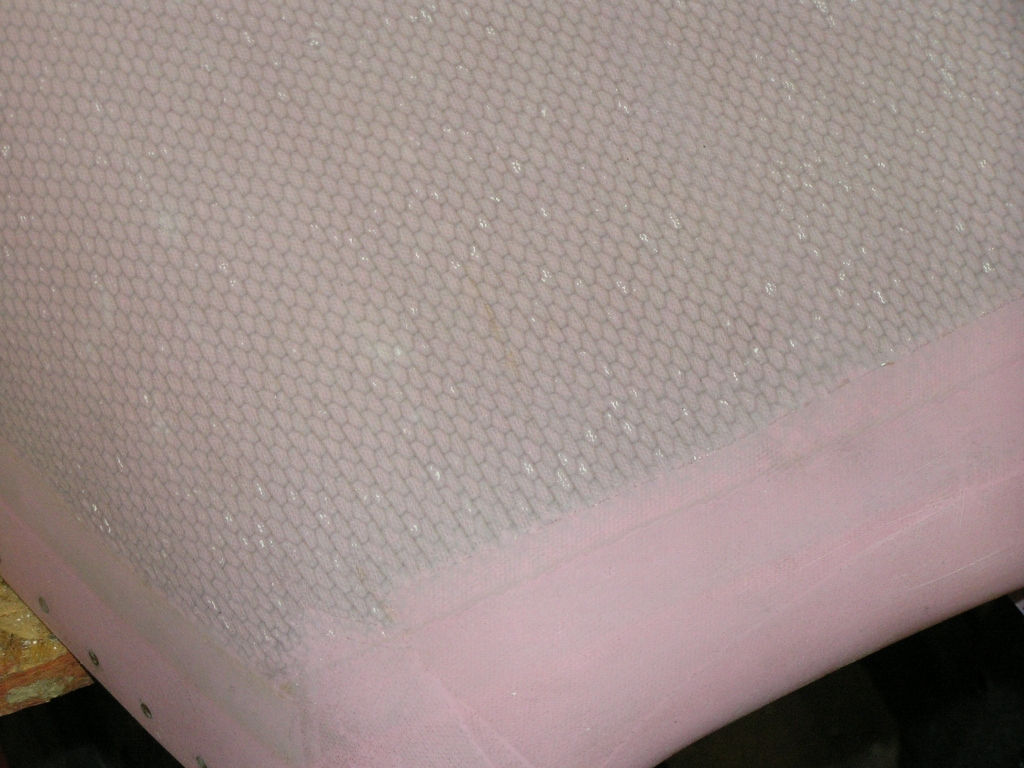 |
2.0 |
| 11/7/08 | I drilled the holes for the Skybolt fastener
grommets to full size. |
1.0 |
|
Installing the Oil
Filler Door |
||
I marked the top cowl and cut out the opening
for the oil door. I then began installing the "hidden
hinge" system and drilled the hinge to the cowl. I
countersunk and riveted the hinge half to the top cowl with
epoxy and micro.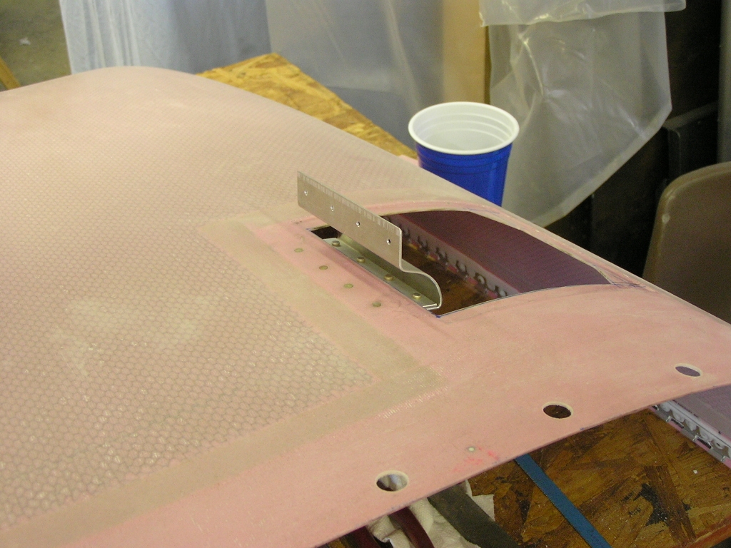 |
2.0 | |
| 11/8/08 | I cut an oil door out of .040 AL to replace the
fiberglass one sent in the kit. I used a drum sander
roller to bend the curve in the door.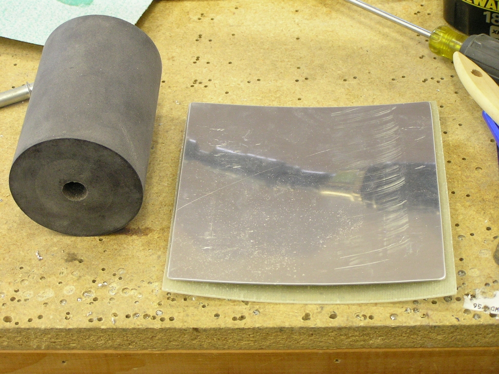 |
1.0 |
| 11/9/08 | I drilled and clecoed the hinge to the oil
door.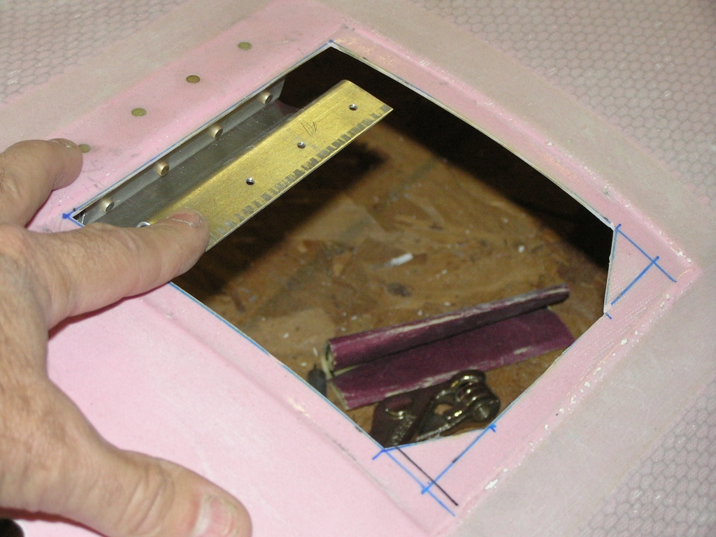
I installed the hidden oil door latch by drilling "weep" holes
for the epoxy to hold. Then, I drilled four holes for clecoes to hold the latch in
place while the epoxy cured. I then mixed a thick mix of
micro and bedded the latch and clecoed. I then glassed the
latch with 9oz. BID and covered with peel ply. |
2.0 |
| 11/13/08 | I was not happy with the gap left by the hinge
so I pulled the hinge pin and removed the door. I then
drilled out the rivets and ground out the micro and removed the
hinge half from where it was bonded to the cowl.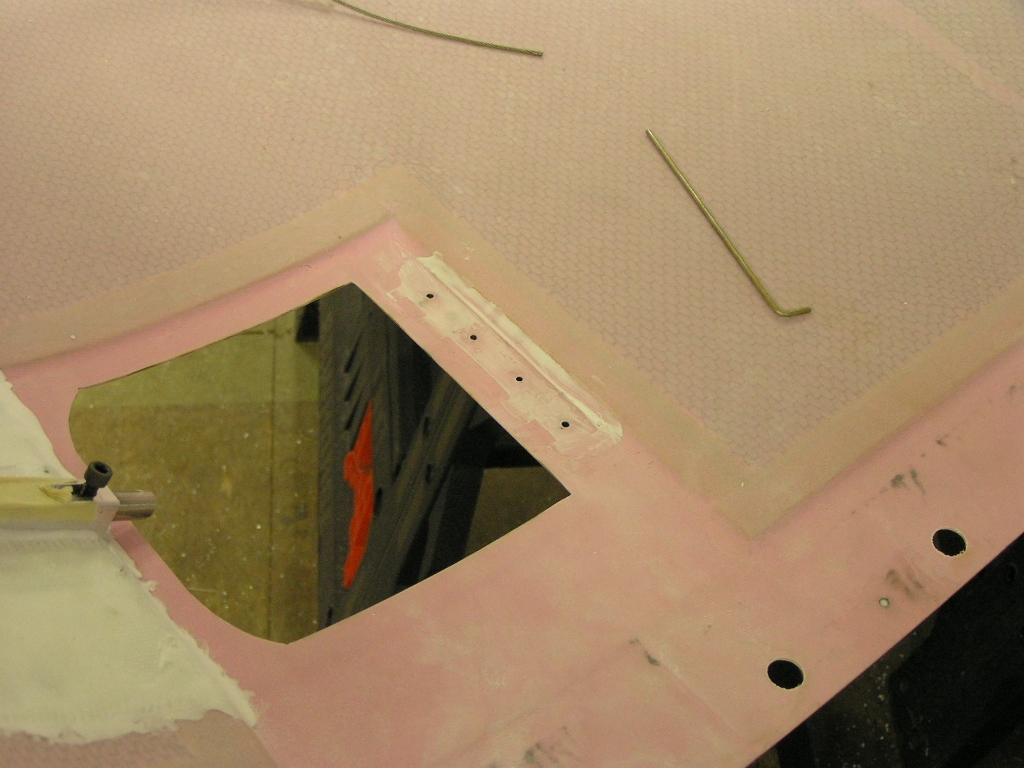 I then
fabricated a couple of shims out of .063" and .028" AL to fit
under the hinge half in order to get the hinge to pull the door
tighter to the cowl when closed. After test fitting, it
appears that I will need both shims to provide the right fit. |
2.0 |
| 11/14/08 | I then adjusted the latch until it held the
door tightly closed. I then countersunk the door and
riveted the hinge and latch.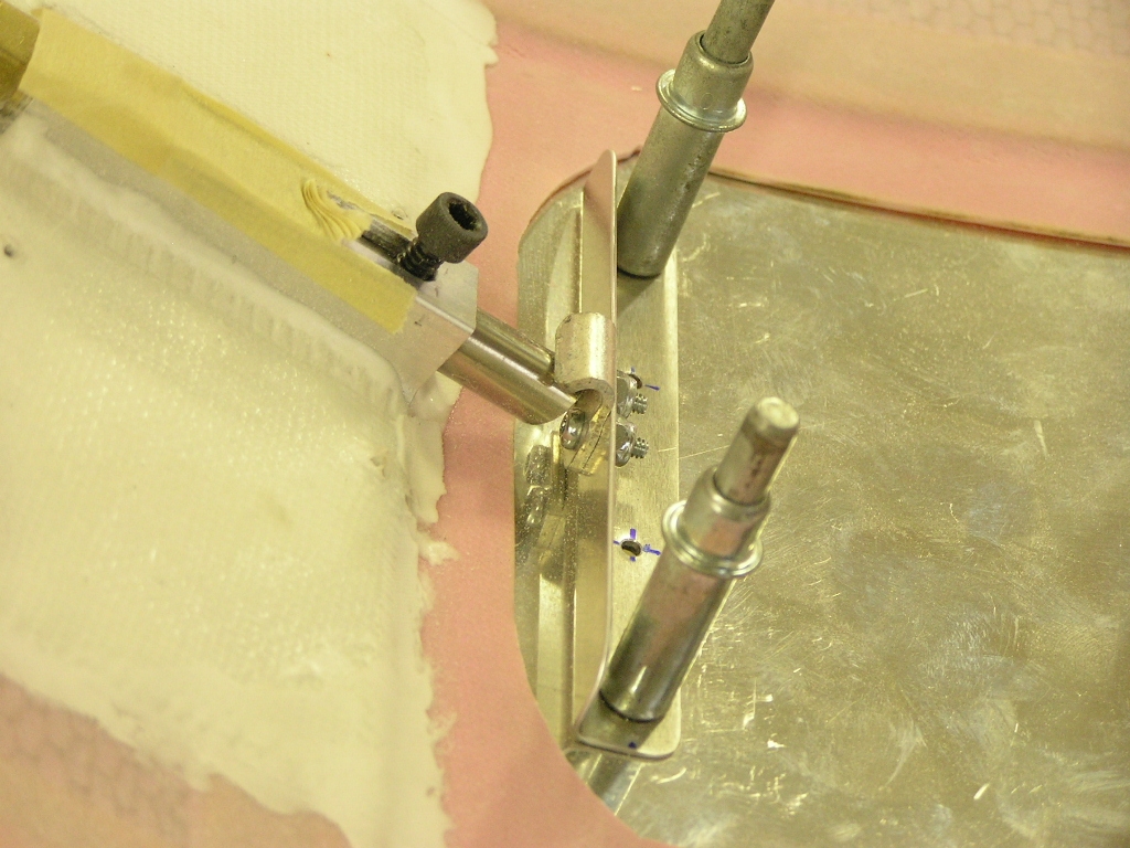 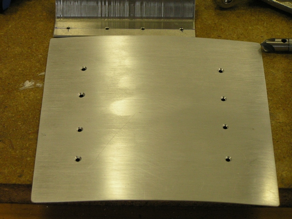  |
2.0 |
| 11/30/08 | Went ahead and applied WonderFil on the spinner
and after wiping off, I sprayed using SEM sanding primer.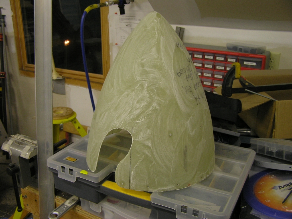 |
1.0
|
|
Next: Firewall Forward 2 |
||
Copyright ©2005-09
Hosted by NTI Networks