
Home
Shop
Tools
Empennage
Wings
Fuselage
Panel
Firewall Forward
Canopy
Wiring
Gretz Pitot Install
Wiring Design
Drop-Down Fuse Tray
Annunciator Fabrication
Auxiliary Battery Tray
Magnetometer Bracket
AFS EFIS 1 Install
Installing Stick Grips
Baggage Area Lights
Control Stick Wiring
Trim System Wiring
Battery Connectors
PTT Quick-Disconnect
Installing Shunts, ARINC
Avionics Wiring
Switch Wiring
TruTrak ADI & A/P
Annunciator Wiring
Engine
Miscellaneous
Wiring
|
Date |
Description of Task | Hours | ||||||||||||||||||
| 10/14/07 | Gretz Pitot Installation | 2.0 | ||||||||||||||||||
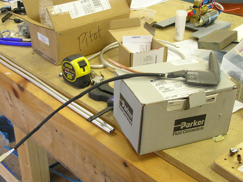
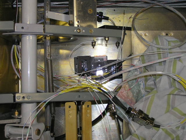
I had to grind the Gretz pitot in order for it
to fit inside the mount tube. I also had to fabricate a
bracket to mount the Gretz electronic control module. The
pitot is designed to work with the ECM but the wires from the
pitot are only about 18" long. The wires must connect to
the ECM as well as the power and ground. I need to install
the ECM one bay out from the pitot tube in order to have access
to it via an inspection hole. I
riveted the ECM bracket in the adjoining bay with the bellcrank.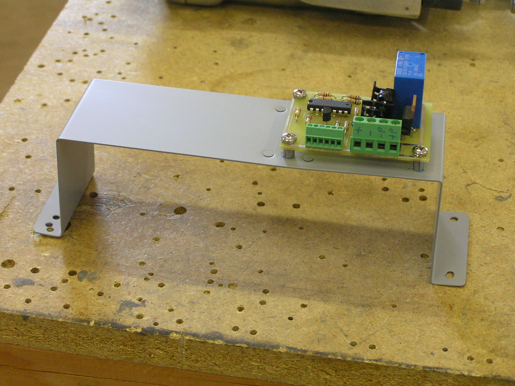 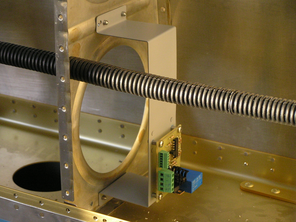
I decided to apply a piece of heat shrink tubing over the wires
coming out of the pitot tube to help protect them when routed
through the rib and around the bellcrank. |
||||||||||||||||||||
| Wiring Design | ||||||||||||||||||||
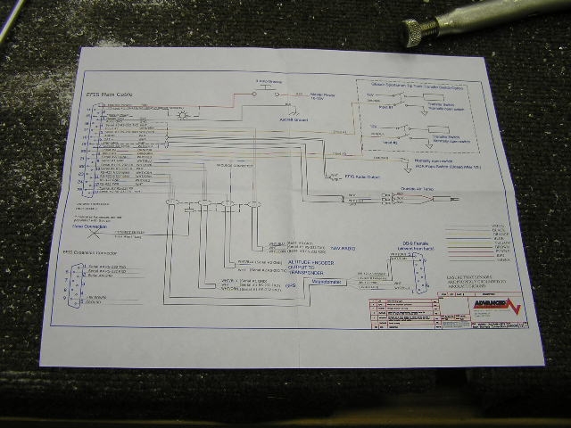
| 12/22/07 | Fellow builder
Mike Behnke and I have been working
together on the wiring design for our individual projects and
both have decided to base our system wiring on figure Z-13/8 as
depicted in the
Aeroelectric Connection.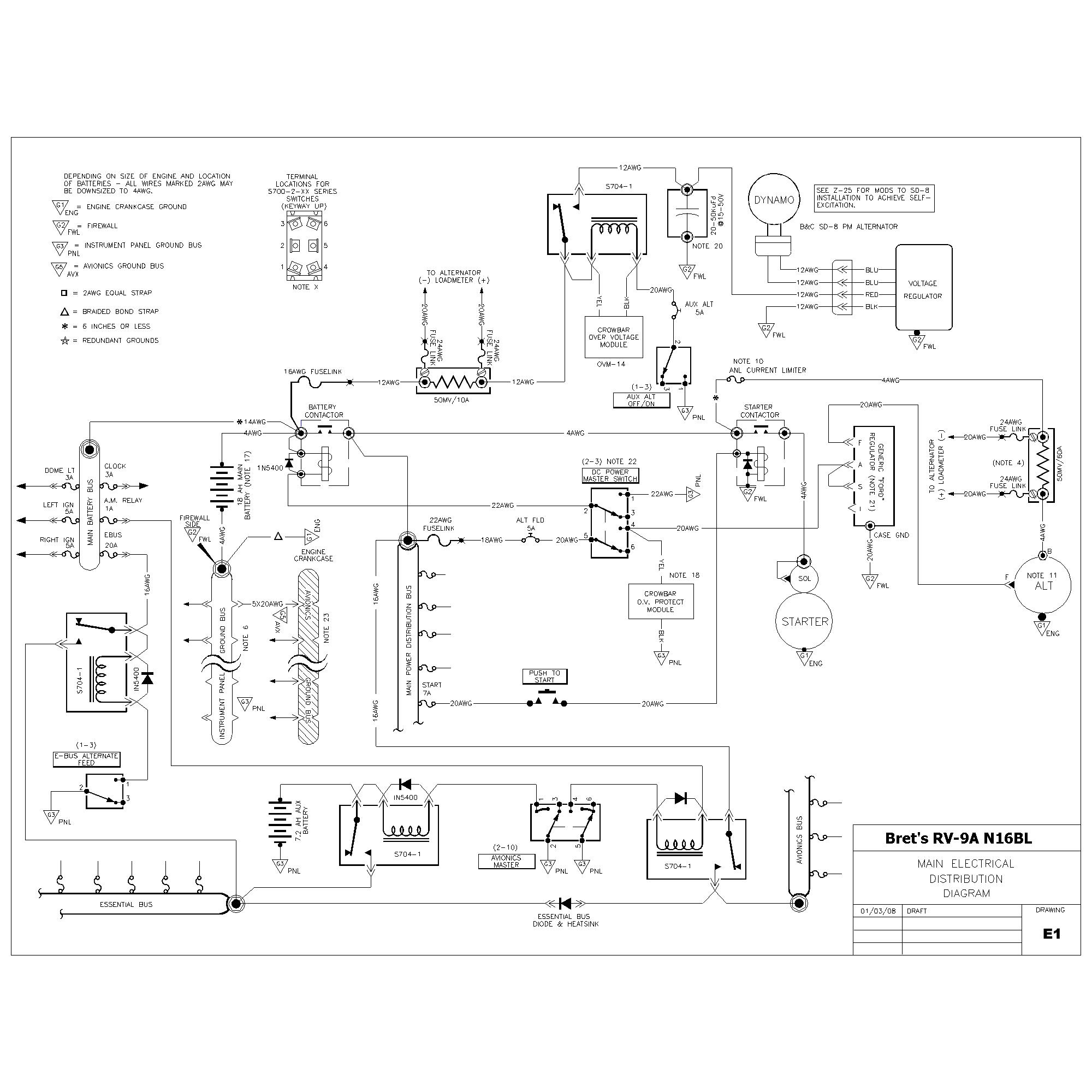
We also want to add an auxiliary battery for powering the
primary EFIS and ADHRS prior to engine start. Mike has
done a fabulous job of combining our discussions and designing
the schematic.
|
|||||||||||||||||||
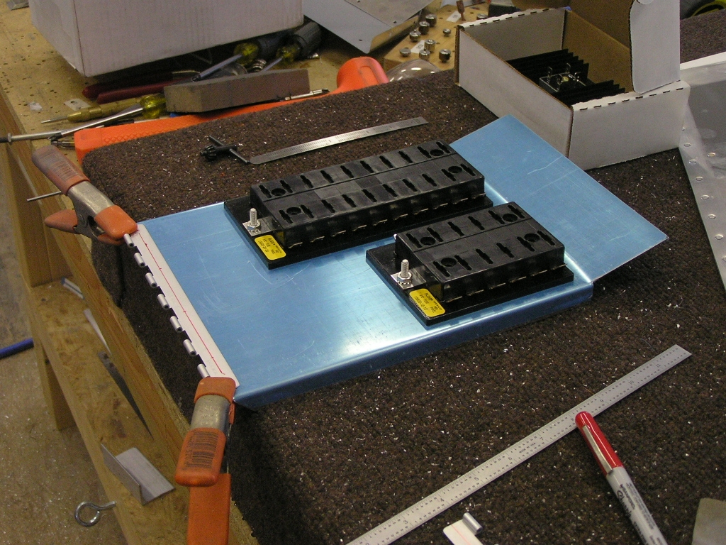
| "Drop-Down" Fuse Bus Tray | ||||||||||||||||||||
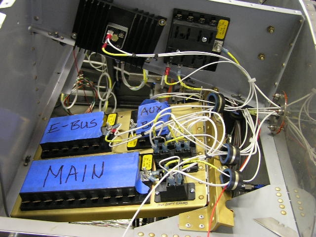
| 1/5/08 | I really liked how fellow
builder Bill Schlatterer designed
his "drop-down" fuse bus panel. I also like how the design
keeps the "fat" wire runs short and all the critical power
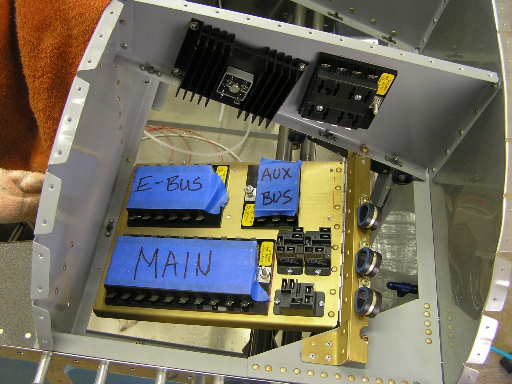
connections in the same area. I started
by fabricating and drilling the hinge angle as well as cutting
out the bus panel out of .040 aluminum sheet. After
bending the flanges I drilled the hinge and test fit. Next, I laid out the 20-slot Main Bus and the
12-slot Endurance Bus (E-Bus). I alodined the components
of the tray and temporarily attached the busses as well as the
D25 E-Bus Diode and heatsink. |
5.0 | ||||||||||||||||||
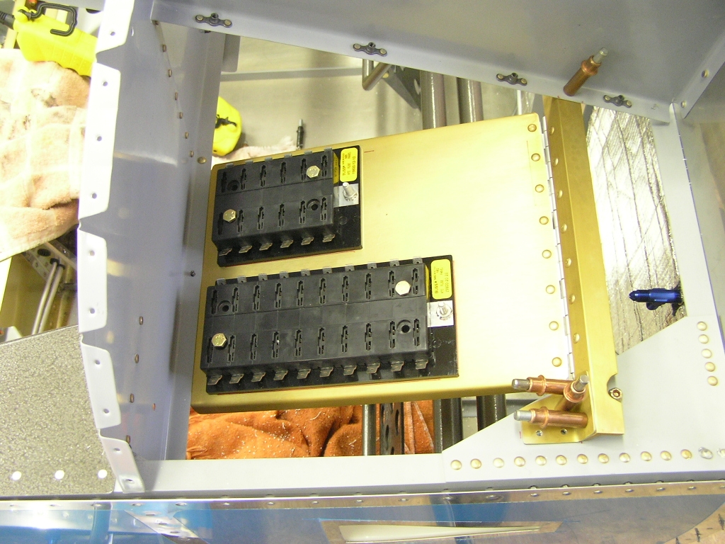
| 1/6/08 | I went ahead and mounted the
Battery Bus and the Avionics Bus to the rib. I also
installed platenuts on the bus tray hinge bar and temporarily
installed Adel clamps. These will be useful for routing
wires later.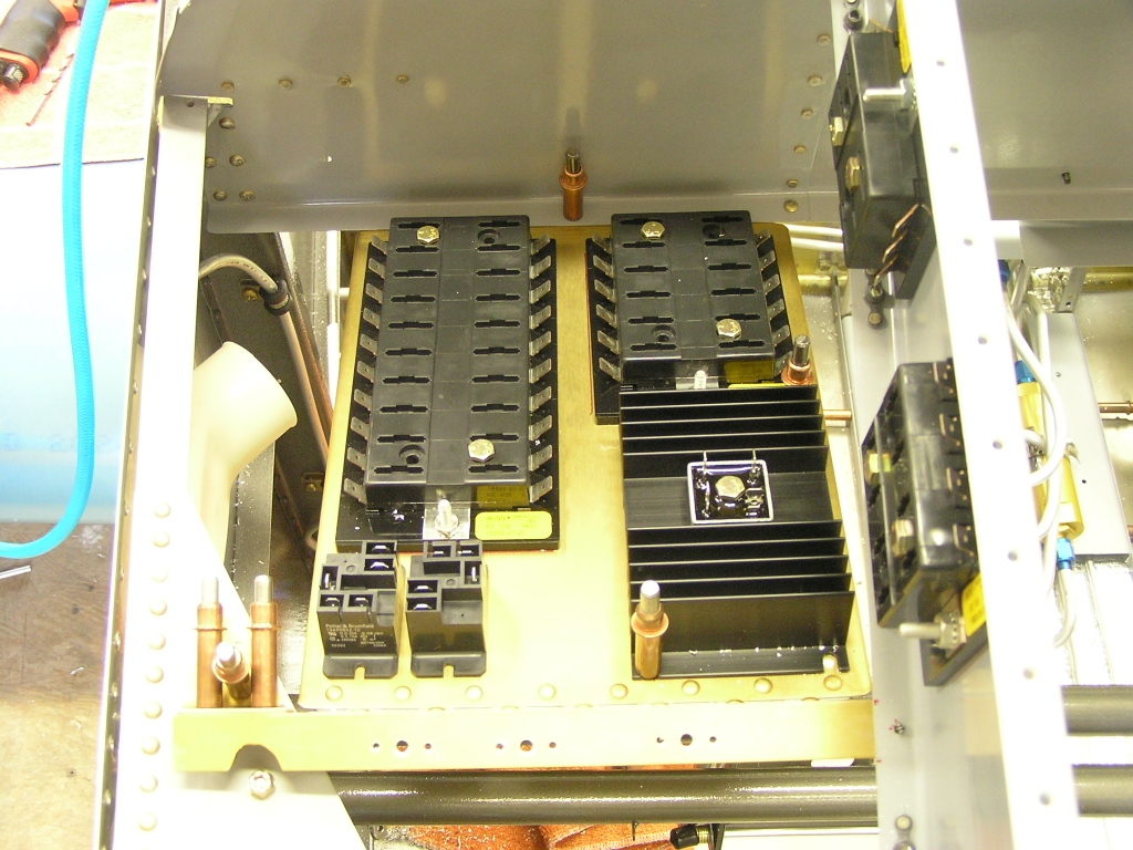 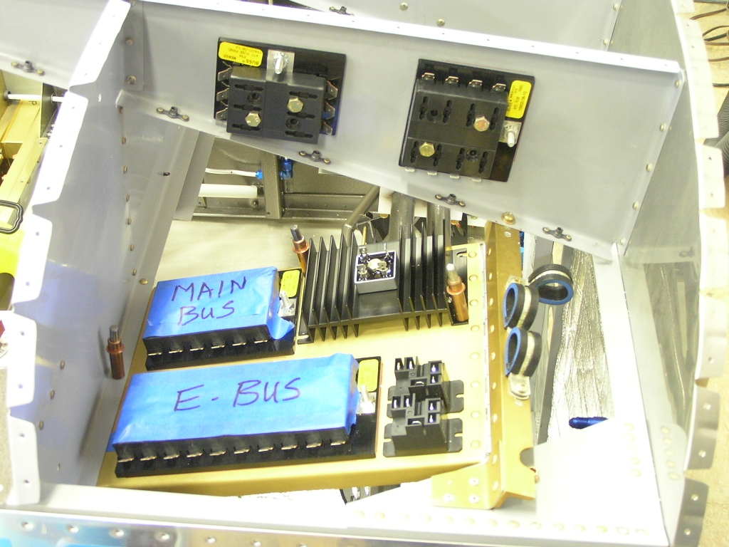 |
2.0 | ||||||||||||||||||
| 1/12/08 | I had ordered some #10 screws as
well as some other hardware in order to attach the fuse busses
as well as the relays so I installed them permanently.
My Finishing Kit is shipped
and should be here late next week! |
1.0 | ||||||||||||||||||
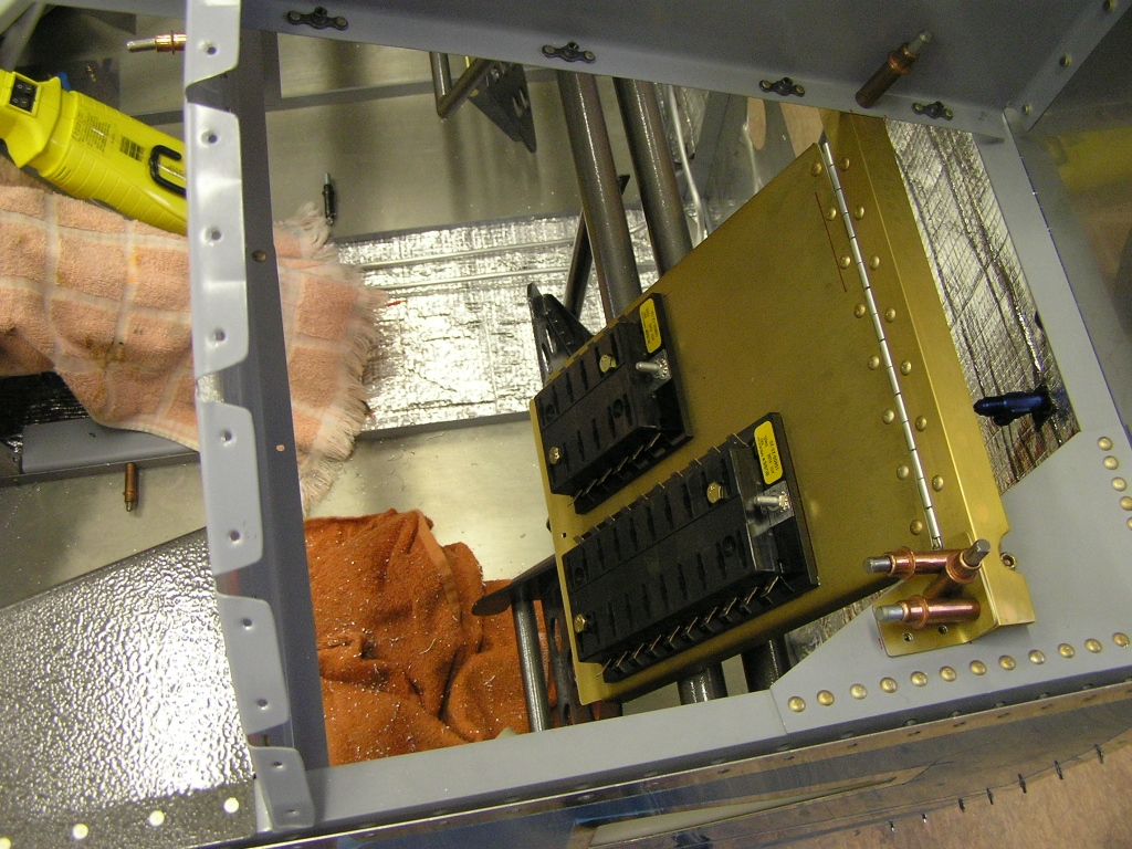
| 1/13/08 | I safety wired the hinge pin on
the bus tray and put more painters tape over the fuse slots to
keep out debris. I also correctly labeled the busses.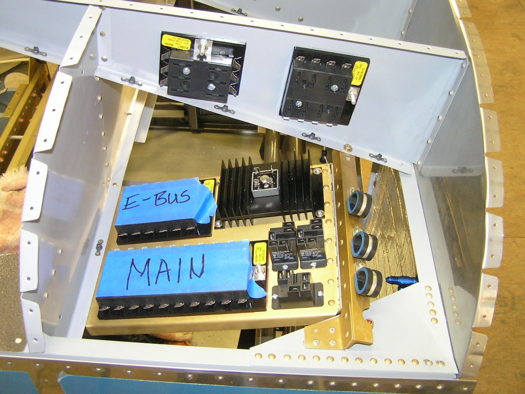
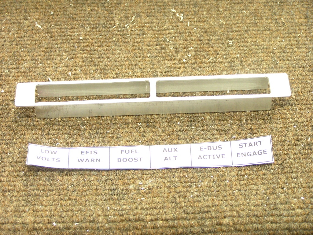
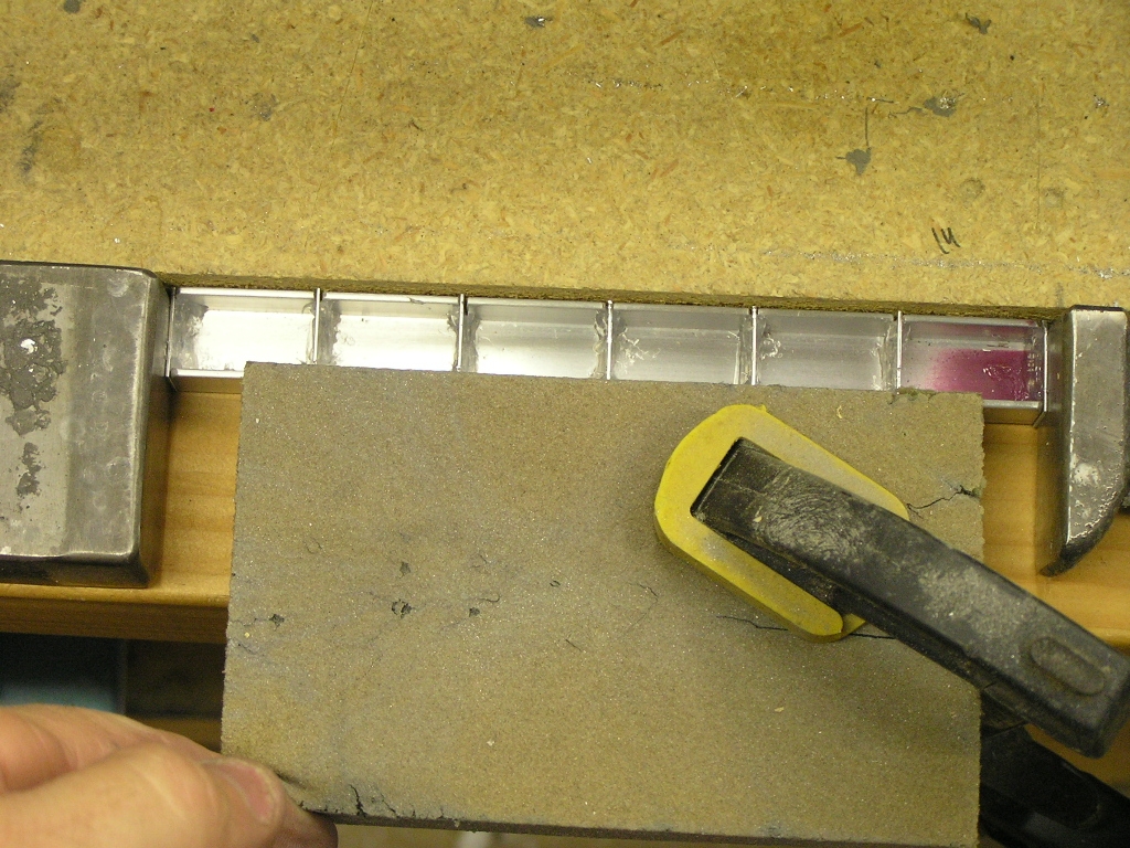
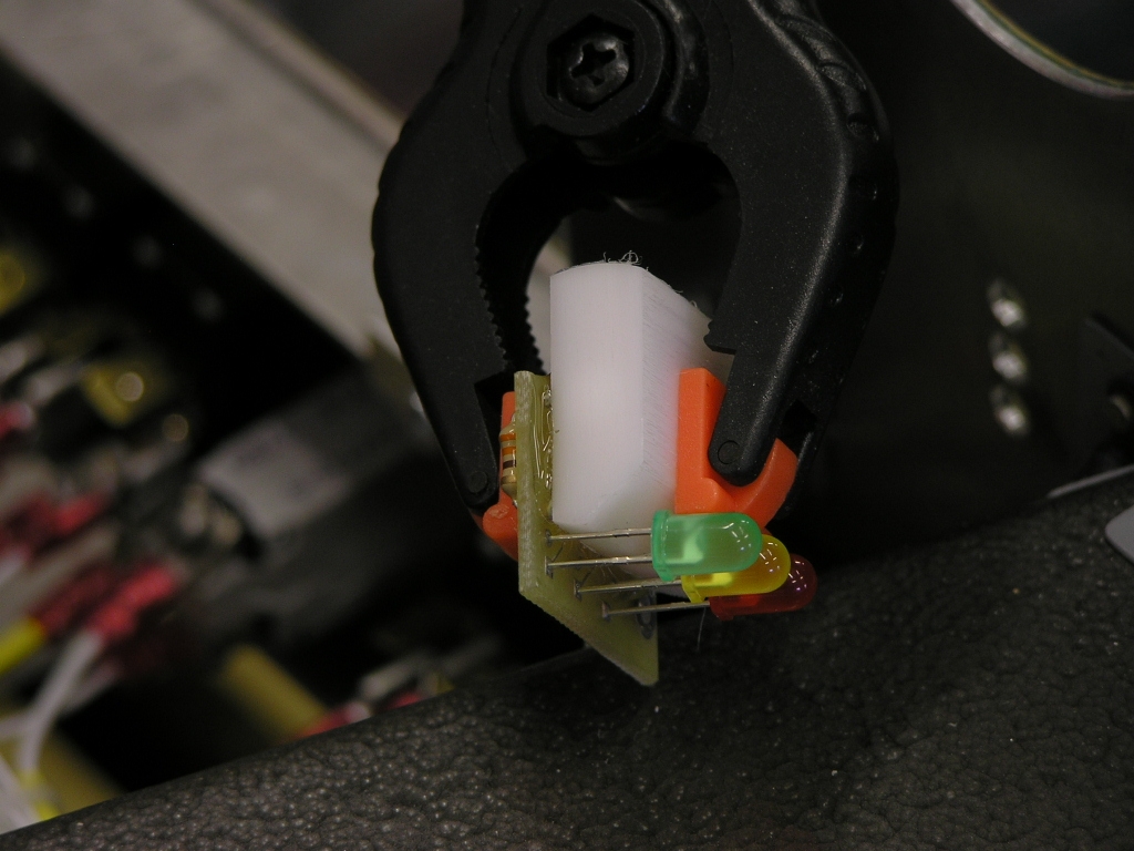
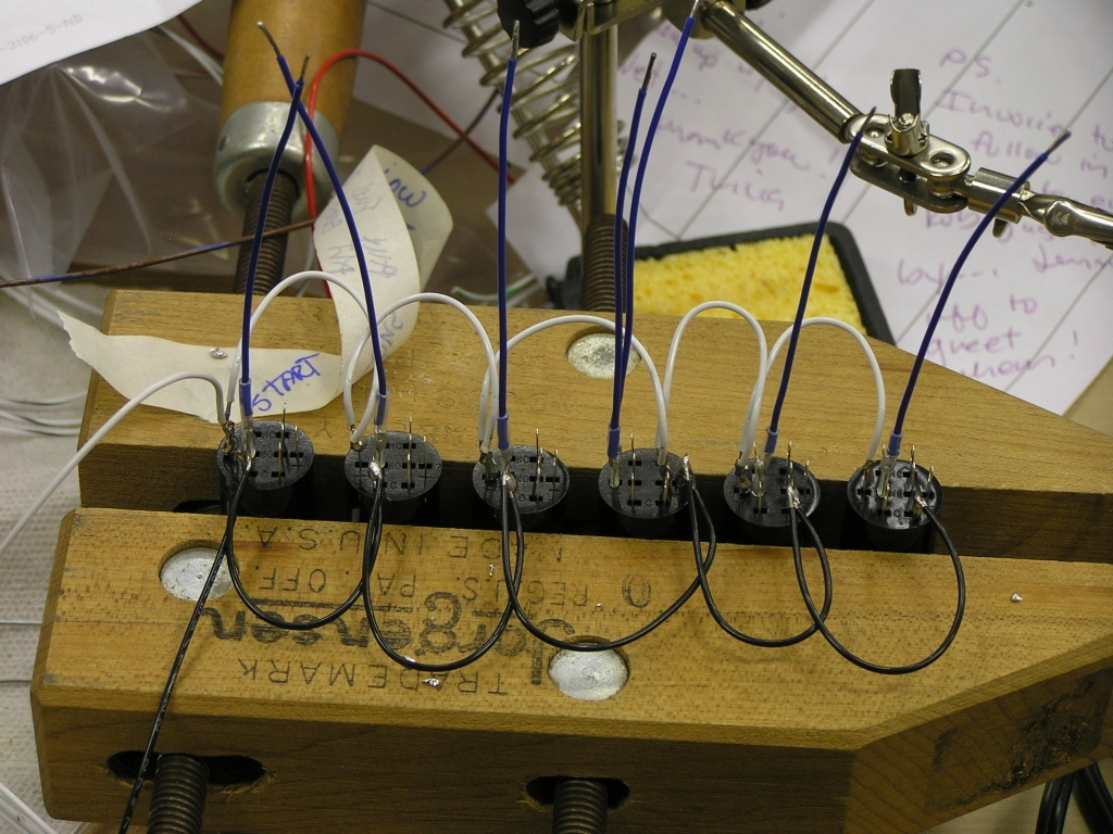
I have been looking for an annunciator light
solution but decided to try and fabricate my own. I really
like the design crafted by Paul Dye.
The design can be found
here.
I bought the aluminum "C" track at Lowes and cut it out using my
band saw. The display will have six lights like this:
We will see how it works. I cut the face first but may need to re-do as I'm not too pleased with the fit and finish.
Next, I cut slots for
the dividers and glued with clear silicon adhesive. |
2.0 | ||||||||||||||||||
| 1/17/08 | I assembled the annunciator
light with the test label. The concept is sound but the
face of the light will need to be re-done to make it more
appealing.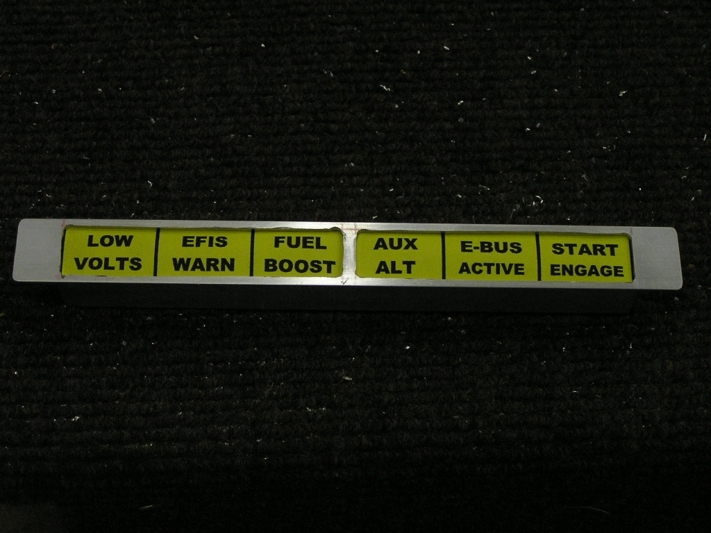 |
|||||||||||||||||||
| Auxiliary Battery Tray | ||||||||||||||||||||
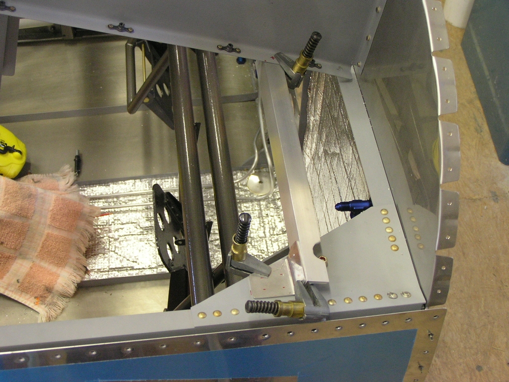
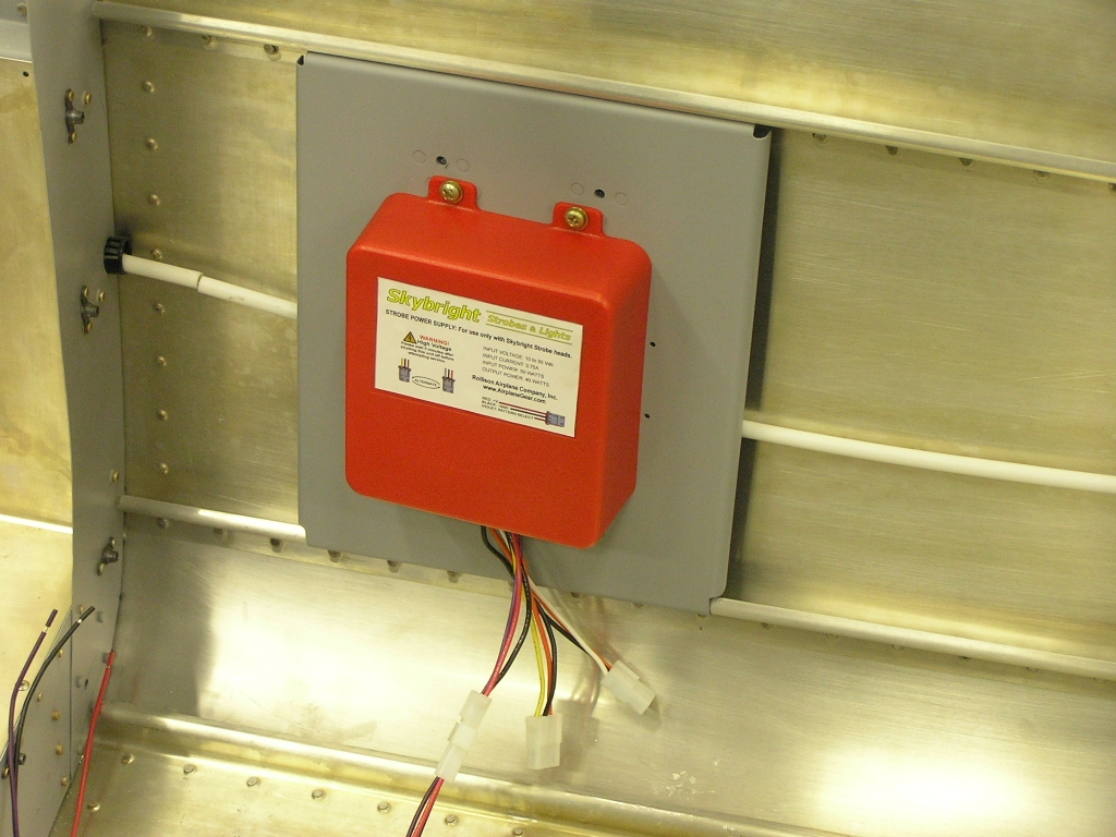
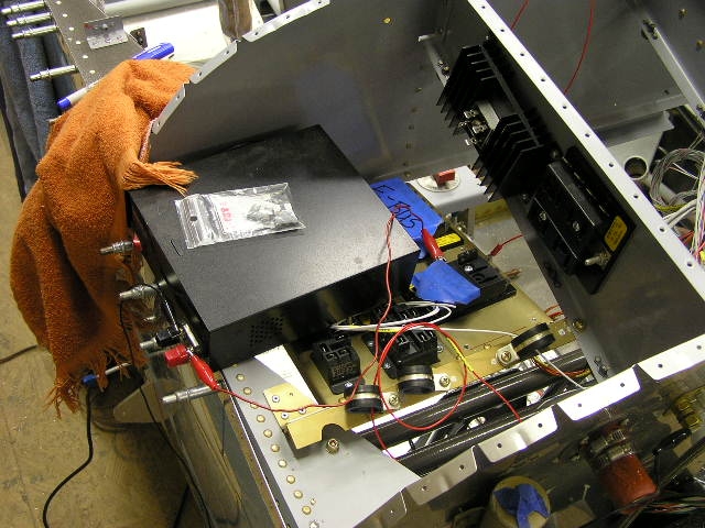
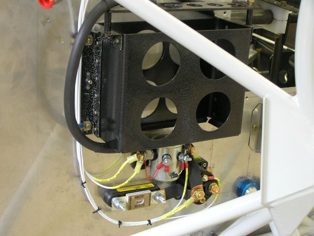
| 1/17/08 | I took the day off today due to
a snowstorm we had here. I decided to tackle fabricating
the bracket to hold the 7.2aH battery I will use as an auxiliary
power source for my E-bus. Thanks go to Mike Behnke for
his idea to build it off the existing rudder brace on the
firewall. I will wait until the battery arrives before
completing the tray to insure a good fit.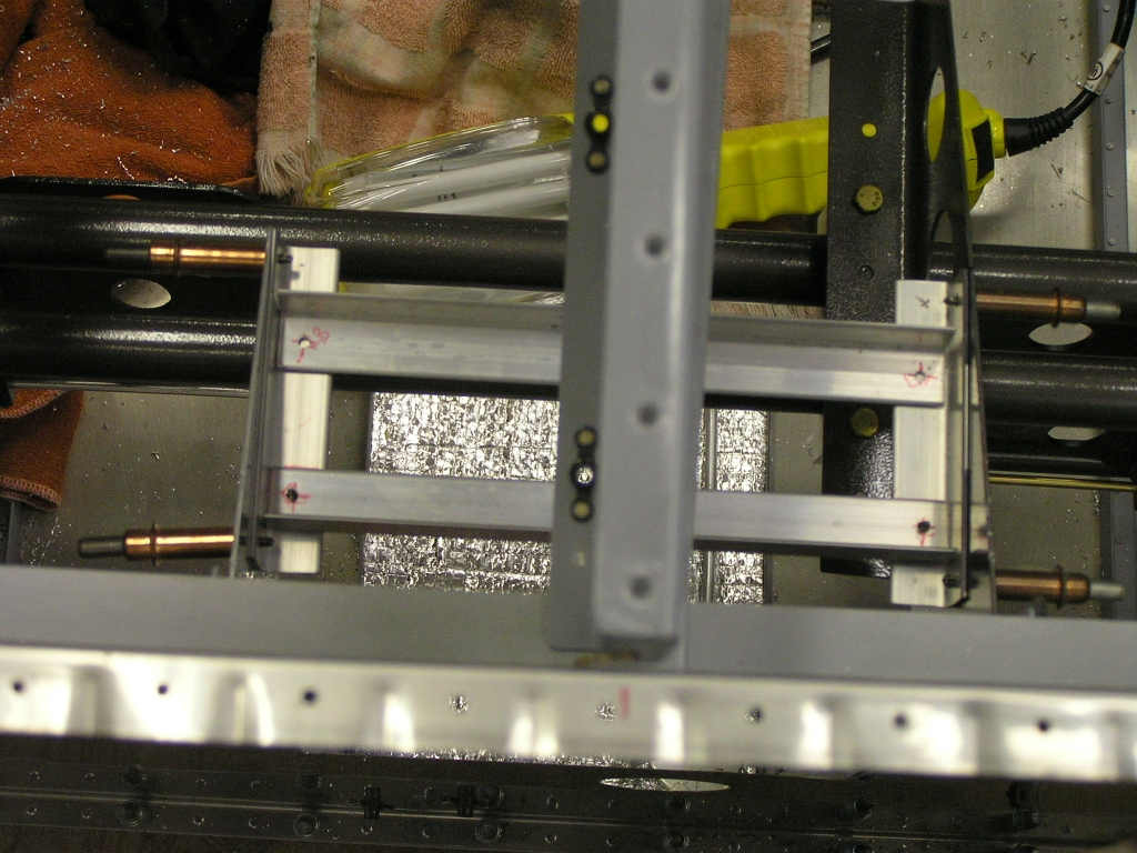
I also went ahead and installed the strobe power
supply. |
2.5
|
||||||||||||||||||
| 1/18/08 | My Finishing Kit arrived today so I will be focusing on the canopy next... | |||||||||||||||||||
| 1/26/08 | I alodined, primed, painted and
assembled the auxiliary battery box.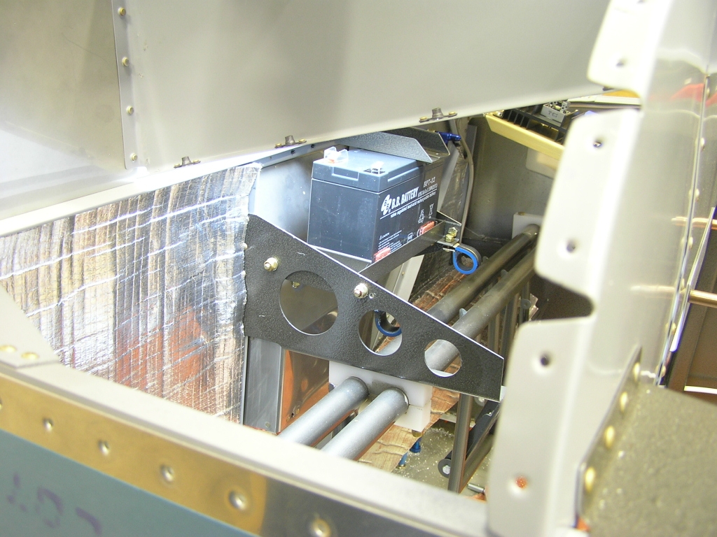 |
1.0 | ||||||||||||||||||
| 2/1/08 | I received another order from
SteinAir of 22AWG wire so I pulled
the five wires for the elevator trim servo through some plastic
mesh. |
1.0 | ||||||||||||||||||
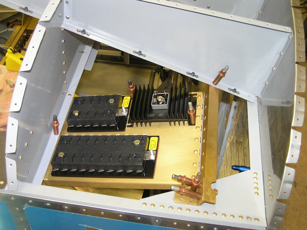
| 3/2/08 | I received the EFIS main wiring
harness from AFS which includes the OAT probe.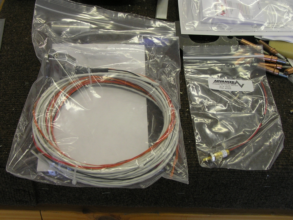
I made a change with the drop-down fuse tray by
removing the E-bus diode and heat sink and installing it on the
rib. I then placed the auxiliary bus on the tray. I
like this arrangement much more. |
1.0 | ||||||||||||||||||
|
Magnetometer Bracket Re-make |
||||||||||||||||||||
| 3/19/08 | I re-made my magnetometer
bracket since I have decided to go with the
Advanced Flight Systems EFIS.
The original bracket was designed for the Grand Rapids
Technologies EFIS. 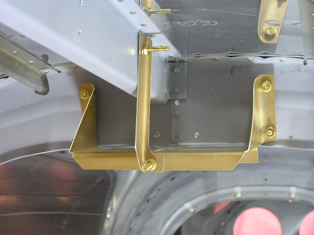 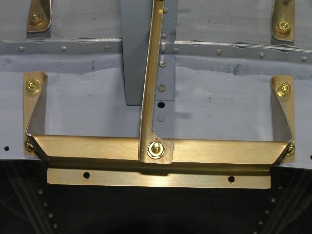 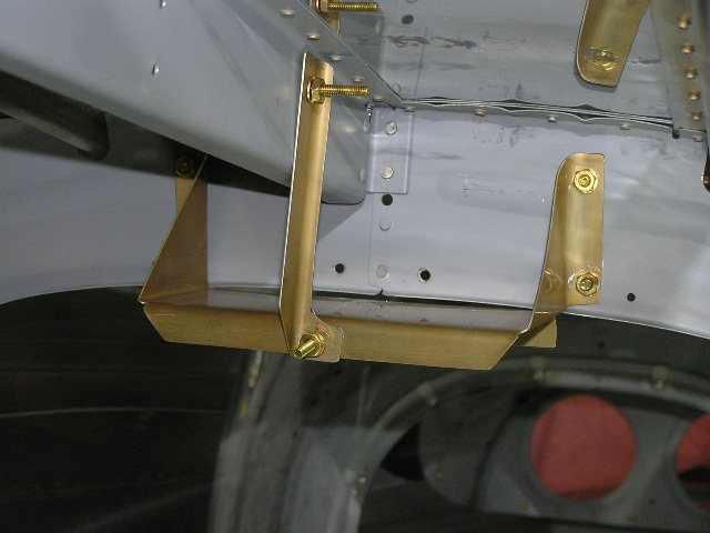 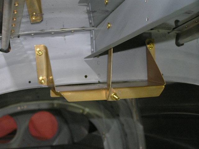
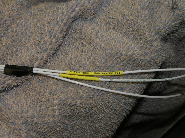
I also ran the 18AWG wires for the strobe power
supply and used my new DYMO RhinoPRO 5000 wire labeler to label
the wires. Sweet! |
1.0 | ||||||||||||||||||
|
EFIS 1 Harness |
||||||||||||||||||||
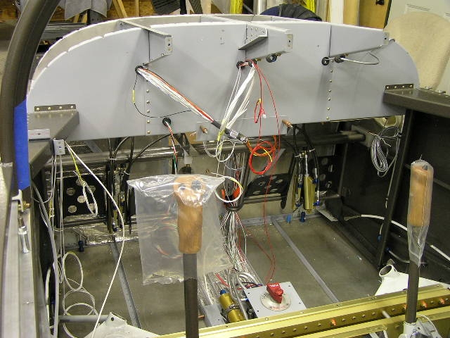
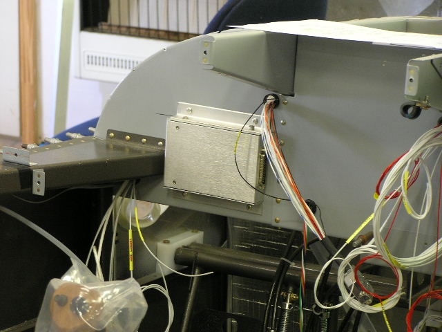
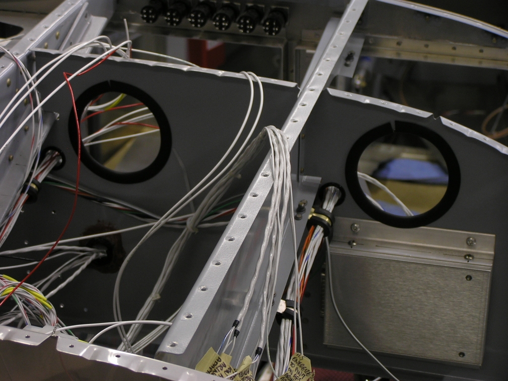
| 3/22/08 | I had previously drilled the
lower flanges of the front deck ribs at 6.0" intervals and
installed platenuts. Today I screwed adel clamps in each
location to support my wiring runs. I also drilled .50"
holes through the subpanel and installed snap bushings.
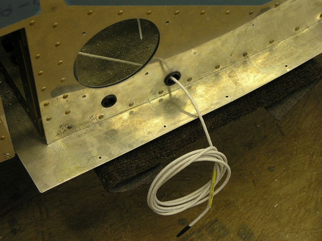
Then, I ran the wires in the AFS EFIS1 harness.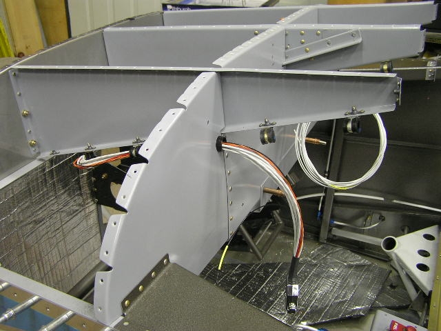 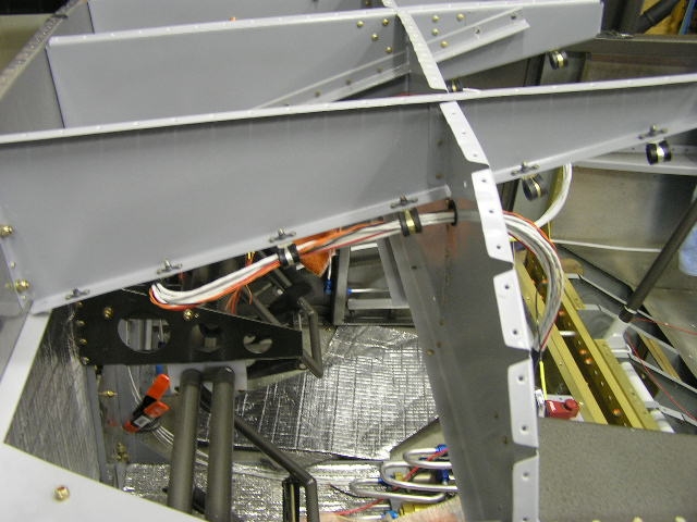 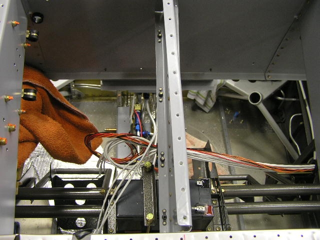 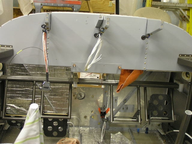
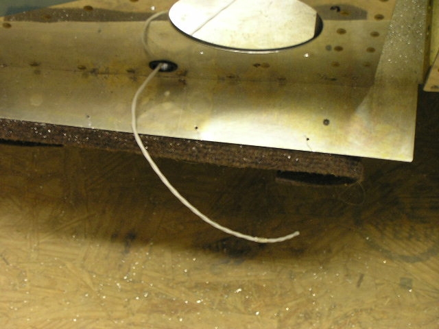
I routed the OAT probe shielded cable through the
center tunnel and behind the spar to the right wing root.
As you can see, if I want to extend the probe farther out on the
wing I will need to splice more shielded cable.
I also found that the magnetometer cable, when
routed the same way, will need to be routed up the baggage
bulkhead support rib and back along the top support rib. I
went ahead and glued several attach points for zip ties.
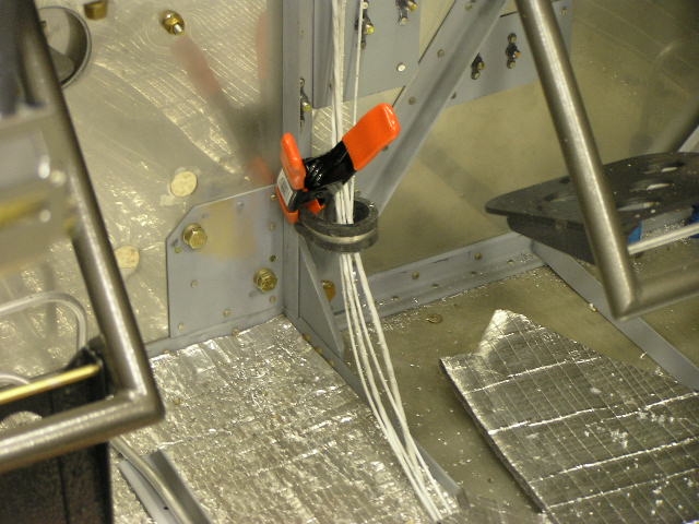
To help get the wire lengths pretty close to
what they will be during final install I clamped an adel clamp
to the firewall support angle. All I have to do is follow
the simple wiring diagram...
I also crimped butt splices on the strobe power
supply and routed the wires through the subpanel. |
2.0 | ||||||||||||||||||
| 3/28/08 | I disassembled the EFIS Main
Cable connector shell and added the following wires and pins:
Pin 14 (Output #1- Warning Light Current Sinking); Pin 15
(Backup Power) and Pin 25 (Serial #2 RS-232 RX). Right now
I know I will need the backup power but have no idea if I will
need the Pins 14 & 25.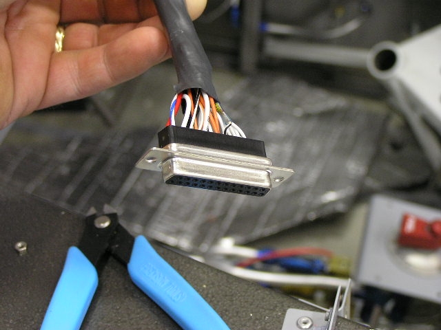
I also crimped the pins and installed a DB-9
Female connector on the Magnetometer cable. |
2.0 | ||||||||||||||||||
|
Installing Stick Grips |
||||||||||||||||||||
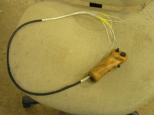
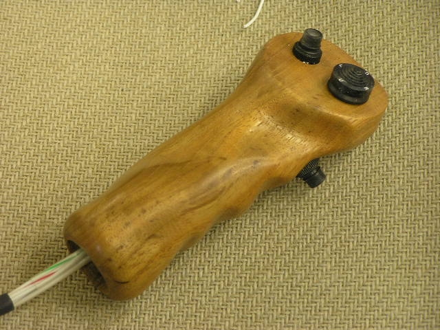
| 3/29/08 | I started by measuring and
cutting 2.00" off the sticks using a tubing cutter. 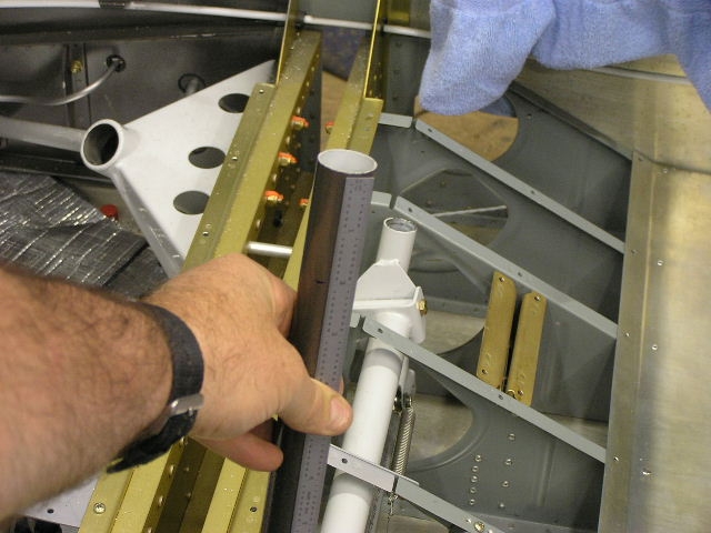 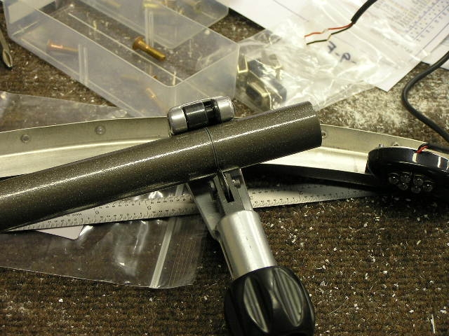
After deburring, I wired the teak stick grips and
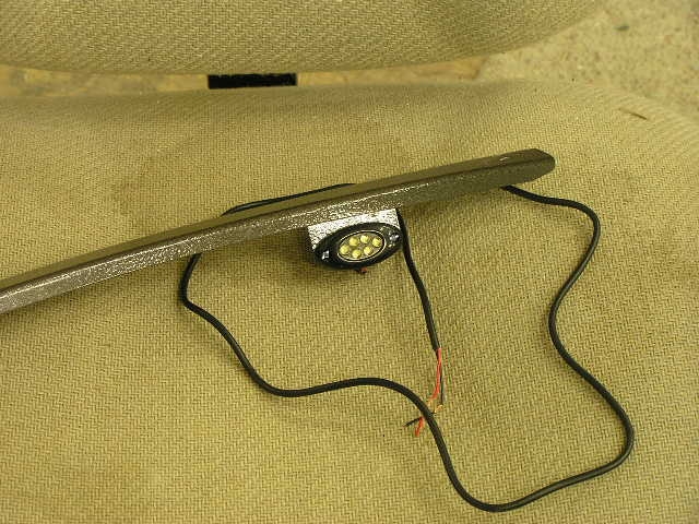
glued them to the sticks using E6000 adhesive. I found some nice surface mount 6-LED lights
at SuperbrightLEDs.com for mounting
in the baggage area. I was going to mount them in the side
panels but Mike Behnke suggested a better location. I
fabricated two small brackets and riveted them to the small top
skin support ribs.
Lastly, I went ahead and installed one of my FPS
firewall penetration kits. Although pricy, these fittings
are well made and will offer the best protection for wiring
through the firewall. |
4.0 | ||||||||||||||||||
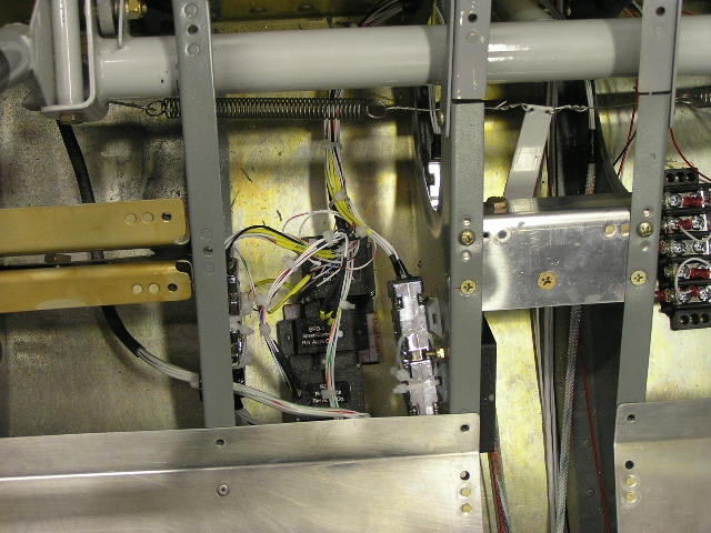
| 3/30/08 | I started on the arduous task of
control stick wiring. Basically, I have the pilot stick
with a 4-way hat switch, Autopilot disconnect and PTT. The
co-pilot stick is equipped with a PTT. The challenge is to
configure the wiring for the sticks in the center tunnel and
connect the elevator servo relay, aileron servo relay, elevator
speed controller, remote speed control switch, A/P disconnect
and PTT's. I finally decided to wire it all together using
D-sub connectors.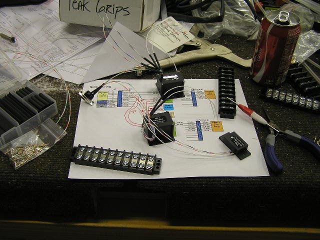 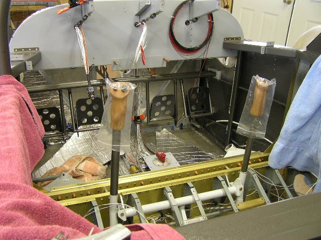
I found some "super strong" hook and loop at
Radio Shack that will be perfect
for attaching the relays and speed controller to the cabin floor
between the ribs. |
4.0 | ||||||||||||||||||
|
Trim System Wiring |
||||||||||||||||||||
| 3/31/08 | I ran the NAV lights power wire
from the panel to a terminal strip junction between the wings
behind the main spar. I also ran a common ground wire for
the NAV lights as well as the trim servos. I checked the
continuity of the stick switches.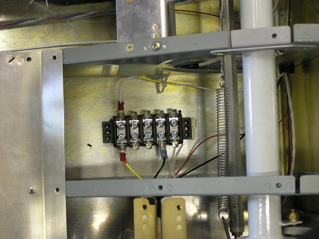 |
1.5 | ||||||||||||||||||
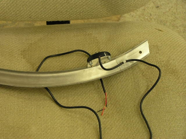
| 4/4/08 | Tonight Lynne and I pulled the
wiring harness I bought from Steinair
for the elevator servo. I added an additional green 22awg
wire by wrapping it around the larger bundle. We then
encased the bundle in the protective covering before installing
in the fuselage.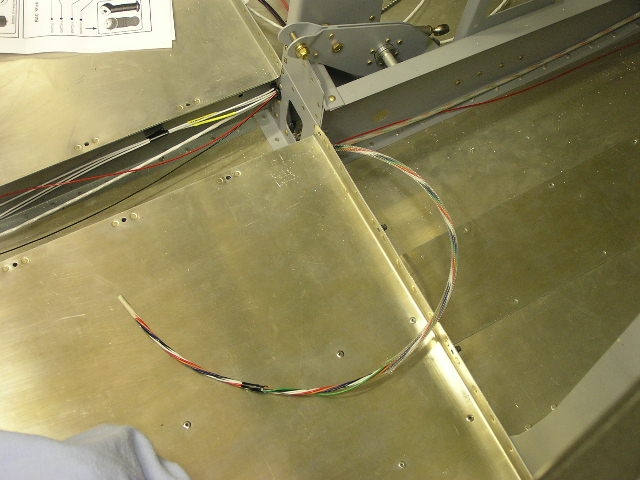 I also ran the three wires to the limit switch
attached to the F-706 bulkhead. |
2.0 | ||||||||||||||||||
| 4/5/08 | Finished up wiring the elevator
and aileron trim servos and elevator trim speed switch to the
stick grip.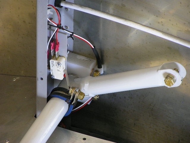 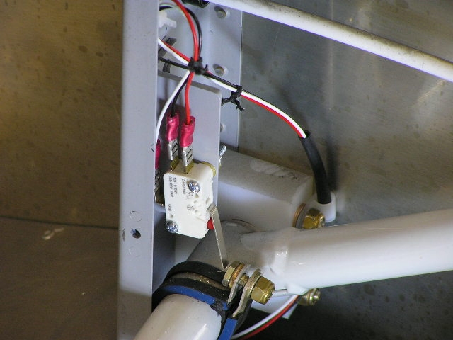
I tested the aileron trim using the hat switch.
I used my 14V power supply to energize a buss in order to test
the circuit. |
2.0 | ||||||||||||||||||
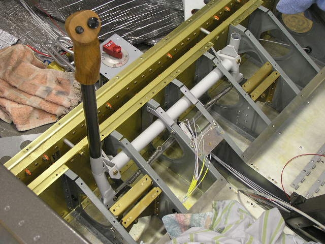
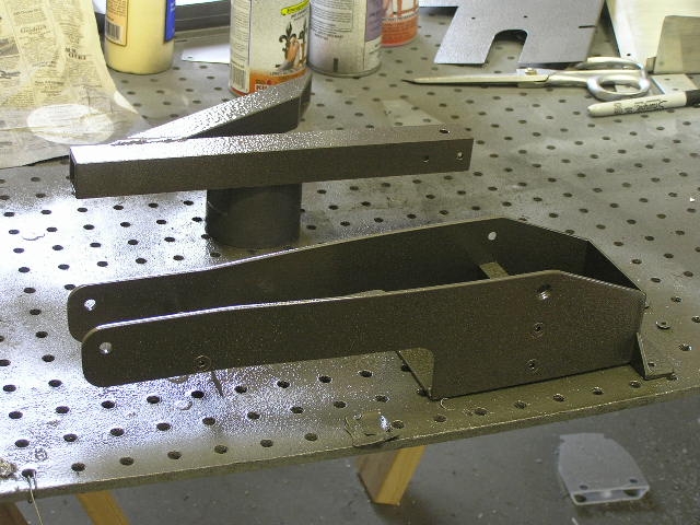
| 4/6/08 | Today I decided to go ahead and
finish torquing all the nuts in the control column and
installing the cotter pins where necessary.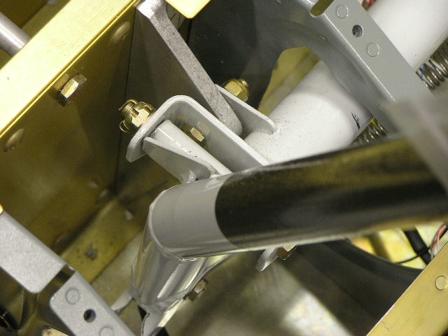
Next, I verified I had maximum stick travel fore
and aft by trimming the seat ribs where the control tube was
binding. The Dremel tool was very handy here. I received my "Thing" from
Mark Phillips
at the "Possum Works" and shot it
with some primer and paint. This thing is really cool.
It will mount between the seats and is a stable structure to
step on when entering the plane so you do not have to stand on
the seats. Once seated, it has a pivoting arm that can be
folded back and becomes an armrest. Oh, it also is a
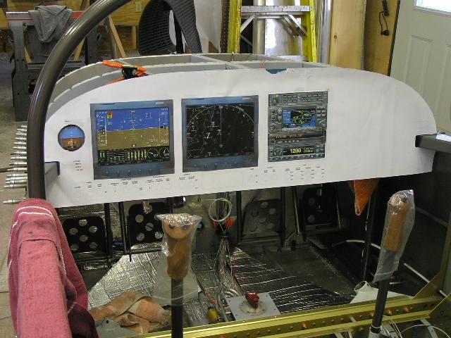
double-cup holder. More on this later. I also went ahead and installed the voltage
regulator for my LED taillight (Perihelion
Designs). I received a full-scale printout of my panel
design from Mike Behnke so I attached it to the panel blank and
added the color cut-outs of the avionics. Pretty cool! Next week I will be going to Sun N Fun so I
hope to snag a few deals. |
4.0
|
||||||||||||||||||
| 4/13/08 | Had a great time at
SnF 2008! I placed my order
for the new Advanced Flight Systems Advanced Deck. I
ordered dual screens (4500EF & 4500EM) with the ARINC adapter,
MAP, XM Weather and Approach charts. I also bought an E-Mag, a SkyTek starter and an SD-8 alternator. Today I finished up securing the trim system
wiring from the sticks. |
2.0 | ||||||||||||||||||
| 4/19/08 | I soldered the connectors on the
two battery cables and temporarily installed them. I am
using 4AWG welding cable for my battery, starter and alternator
"heavy" wire. This wire is multi-stranded and very
flexible as well as having outer insulation that is designed to
be burned, stretched, drug over rocks and be run over by trucks.
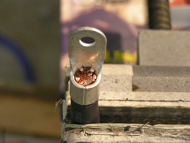
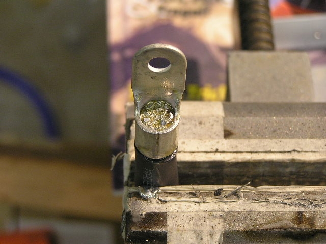
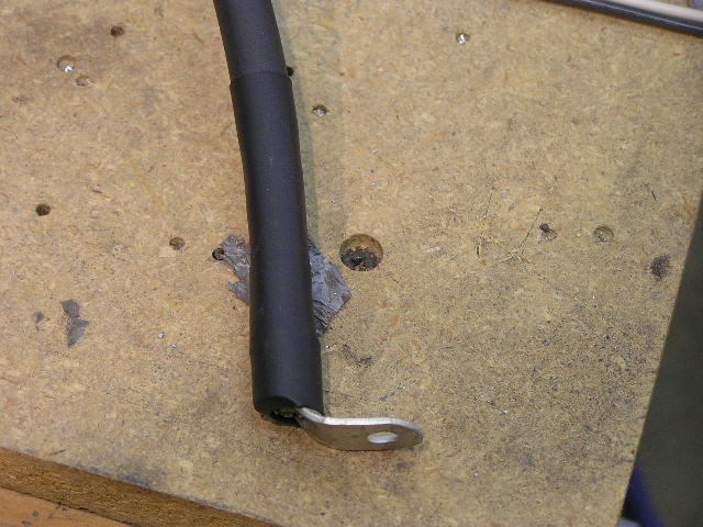
It ought to be good in an airplane. Installing Battery Cable Connectors I stripped the insulation back 1/2" and
clamped the cable in a vise. I slipped the connector over
the wire and cut 1/2" pieces of 12AWG electrical wiring and
"filled the gaps". I found that it took about 5 pieces in
order to fill the connector. I used a propane
torch/soldering iron I bought at Radio
Shack and heated the connector until the solder would
"suck" into the wire. I just kept adding solder until I
would see it drip out the bottom of the connector. After
cooling, I added a piece of shrink tube to finish it off.
What I liked best about fabbing my own cables is I was able to
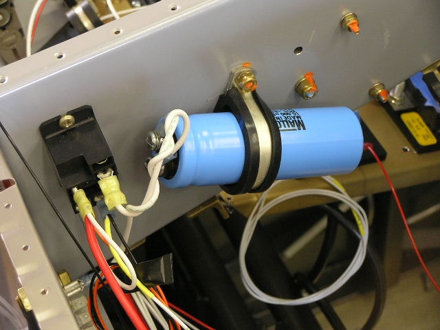
orient the connectors to their exact positions. I then installed the aux alternator relay and
capacitor. |
2.0 | ||||||||||||||||||
| 4/20/08 | More wiring... I am basically
taking my wiring schematic and running one wire at a time.
I'm also trying to keep all my wiring runs consistent so I can
tie it all together after all the wires are installed.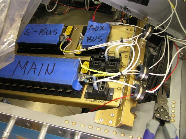 |
6.0 | ||||||||||||||||||
| 4/26/08 | More wiring... I received the
SD-8 alternator and regulator from B&C
so I went ahead and installed the regulator as well as drilled
the "pass-through" for the EGT/CHT probe and alternator wires.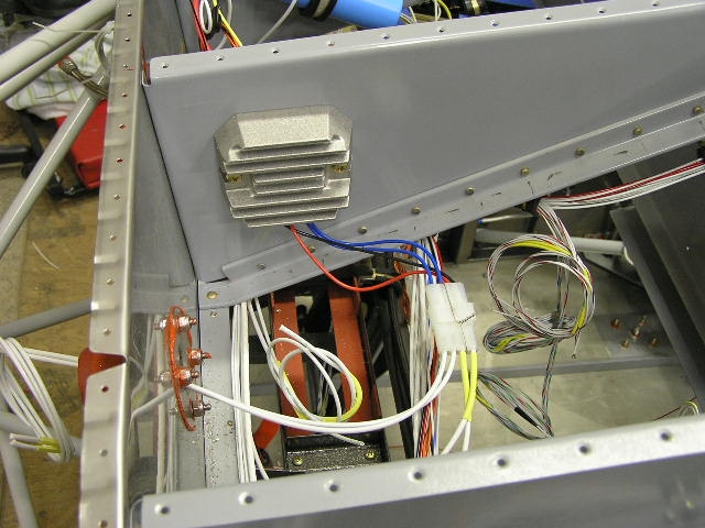 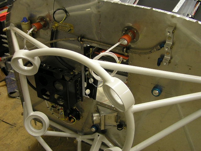
I also received some additional terminals so I
was able to finish wiring the relays and battery contactor. |
2.0 | ||||||||||||||||||
| 4/27/08 | I crimped the connectors on the
RG400 for my COM1 and COM2 antennas as well as ran the antenna
cable for the ELT.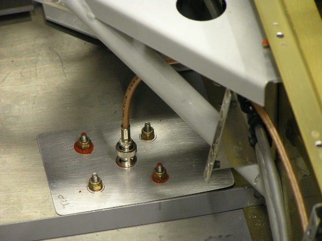
I pulled the shielded cable for the Gretz pitot
indicator out the fuse side for running in the wing. I
also ran the boost pump wiring up to the panel. |
3.0 | ||||||||||||||||||
| 5/16/08 | I received my avionics wiring
harnesses from Stark Avionics today. Tony was great to
work with and was able to wire the harness for all the avionics
I will be installing.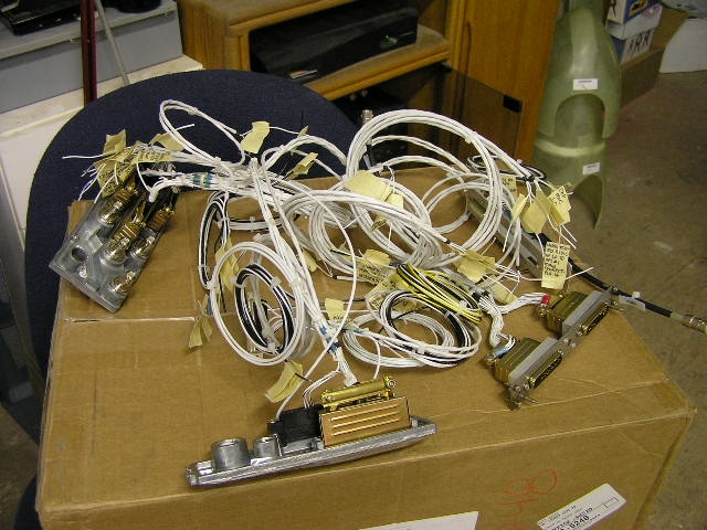 |
|||||||||||||||||||
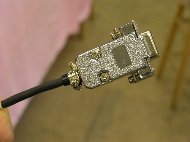
| 5/24/08 | I have to wait until Lynne can
help me drill the canopy side skirts so I decided to solder the
mini jack and plug for the co-pilot PTT on the removable control
stick.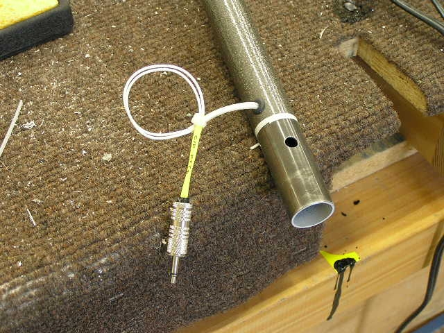 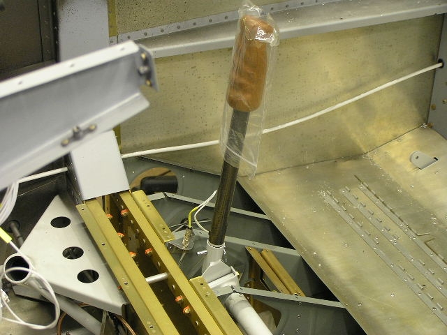 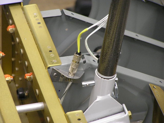 |
1.0 | ||||||||||||||||||
|
Installing
Shunts, Transducers and ARINC |
||||||||||||||||||||
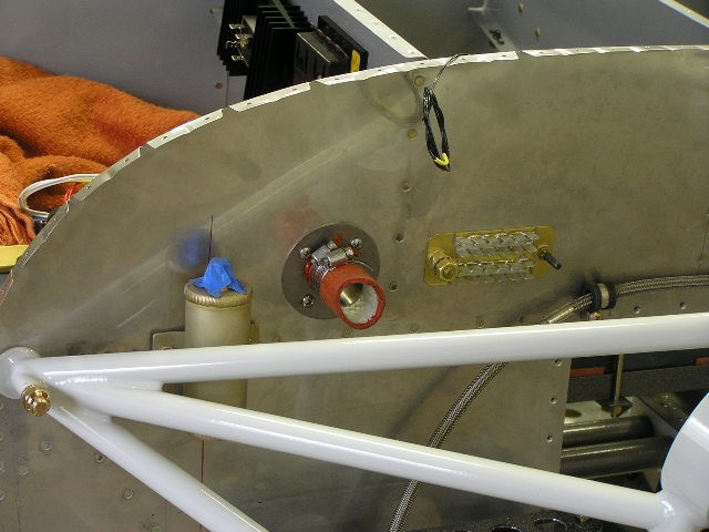
| 7/4/08 | Today, while sealing the panel
veneer, I installed the two shunts for measuring the current
from my main (60A) alternator as well as the 8A SD-8 backup
alternator.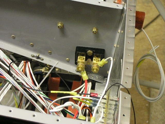 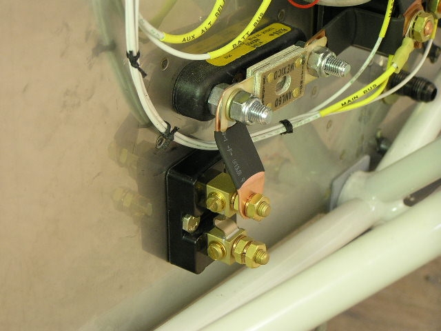
I also installed the oil pressure transducer and
the fuel pressure transducer to the manifold Lastly, I installed the ARINC box to the
subpanel. I had to fabricate some .075x.075x.064" AL angle
pieces to attach to both sides of the module. I don't have
the EFIS display units yet so I can't tell if there is a
clearance issue... No biggie, this box can be mounted just about
anywhere. |
2.0 | ||||||||||||||||||
|
Avionics Wiring |
||||||||||||||||||||
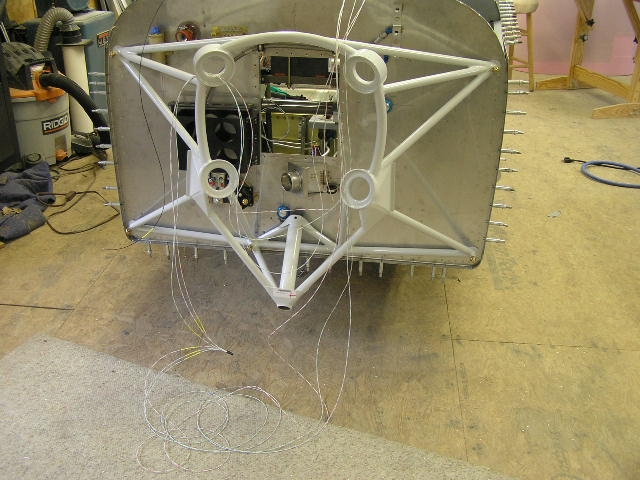
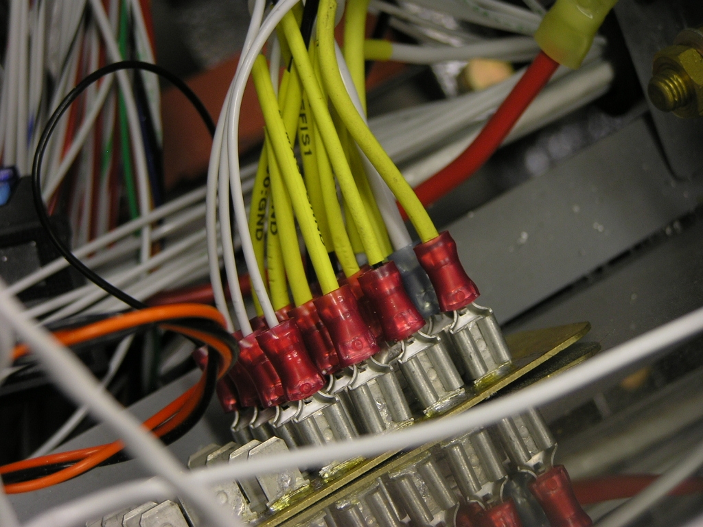
| 8/27/08 | I have installed the back panels
on my avionics trays and started trying to route the plethora of
wires. I started by pulling all the grounds and connecting
them to the panel ground tabs. I then began connecting the
power wires to the appropriate bus. I am labeling every
wire termination as I go. This is a time-consuming
process, especially in a shop that is over 92 degrees.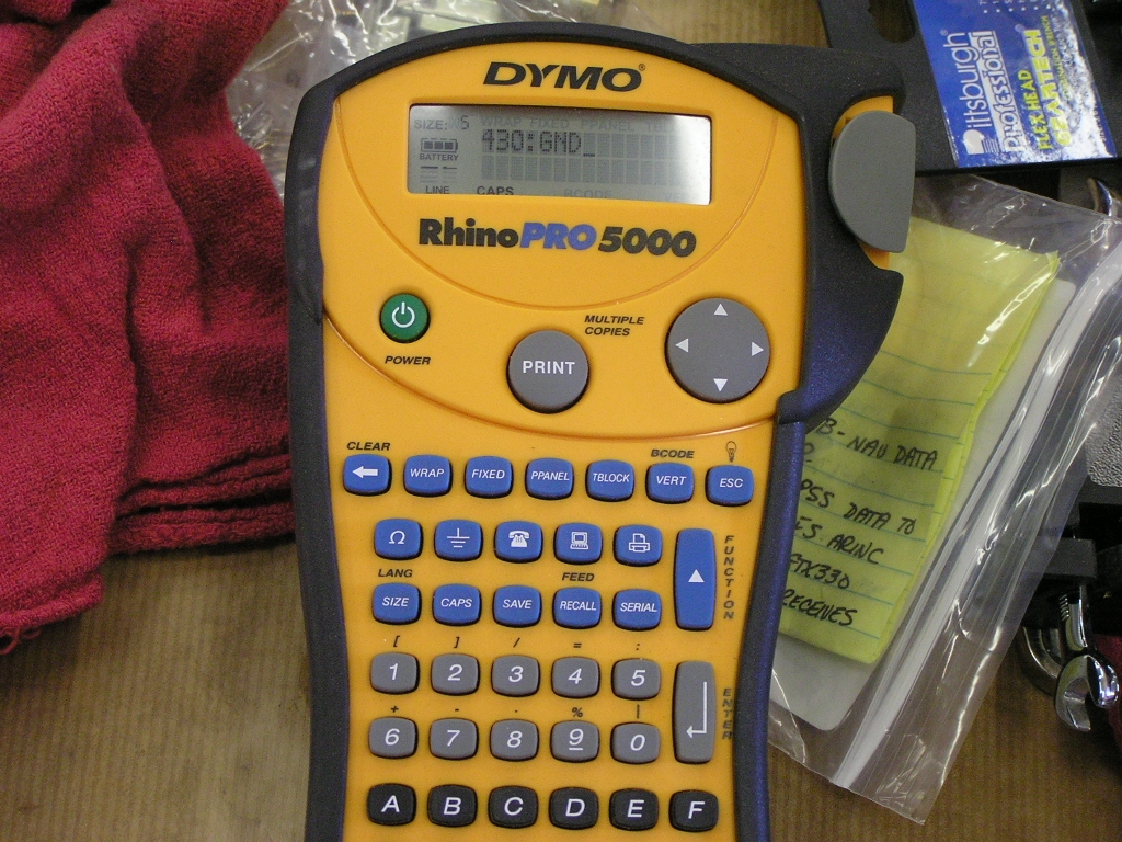 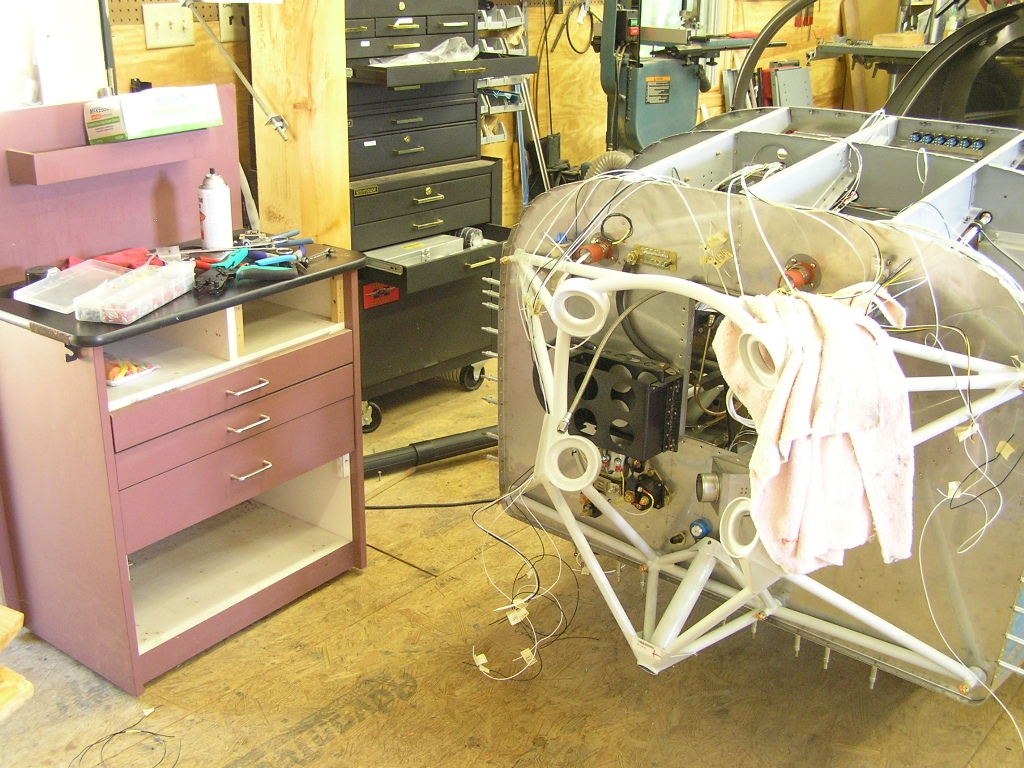 |
|||||||||||||||||||
|
Switch Wiring |
||||||||||||||||||||
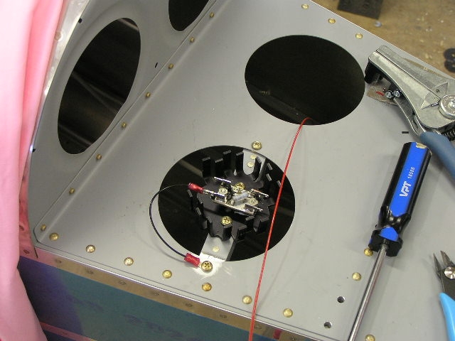
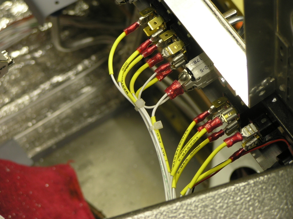
| 8/1/08 | I began to route the wiring for
the switches. I had to fabricate a 22AWG fuse-link for the
Master switch to the Main Bus.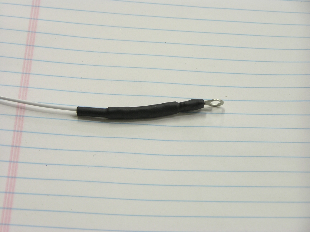
I temporarily zip-tied the bundles as I went in
order to keep the runs the correct length and make the routing
as neat as possible. I am also labeling each termination
with shrink tube using my Dymo Rhino 5000
labeler. I also cut two large 4.0" holes in the
subpanel for connector access to the two AFS EFIS screens.
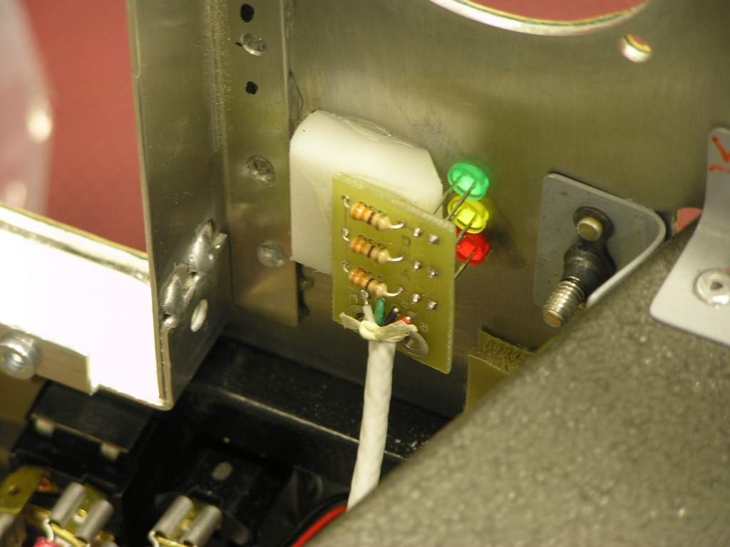
I used a rubber trim to seal the edges. Finally, I fabricated a piece of delrin
material to act as a spacer and mounting block for the Gretz
pitot tube LED annunciator. I used E6000 epoxy to mount it
to the rear of the panel. |
6.0 | ||||||||||||||||||
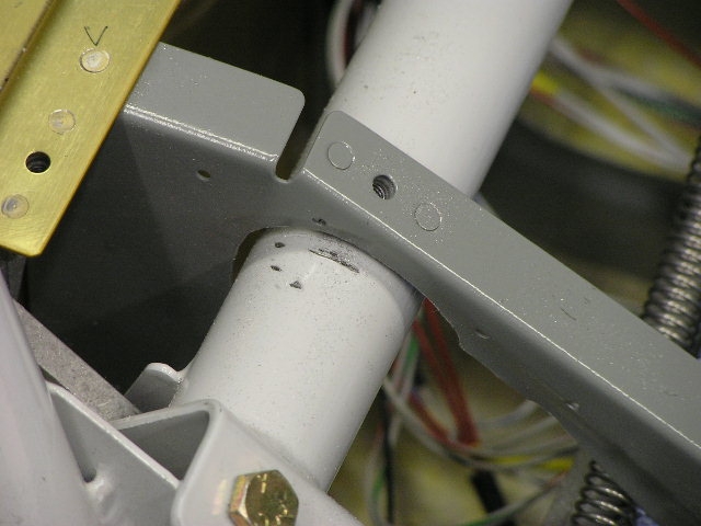
| 8/3/08 | In order to accommodate the AFS
Advanced Deck EFIS screens I needed to trim one of the forward
cabin ribs. I used my Dremel tool and cut out just enough
of the rib in order to allow clearance. I then riveted a
full-length section of .128" AL angle.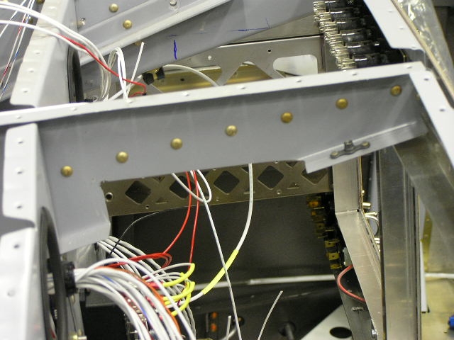 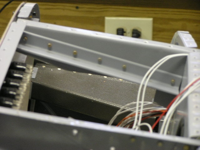 |
2.0 | ||||||||||||||||||
| 8/7/08 | I received another order for
heat shrink labels as well as extra 20AWG wire and push-on
terminals. I find that I am having to re-do many of my
wire runs because I have made the runs too long. I am now
tying off the runs a few wires at a time using zip ties and
re-crimping new terminals. It is a tedious process but
will look well-organized when I am finished. |
2.0 | ||||||||||||||||||
| 8/8/08 | Continued switch wiring...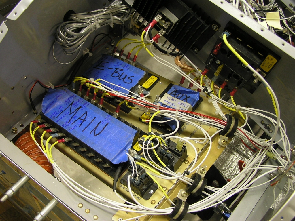 |
4.0 | ||||||||||||||||||
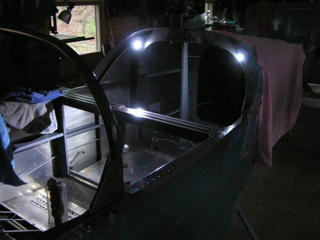
| 8/9/08 | Wrapped up the switch wiring.
Installed LEDs in the subpanel for interior lighting.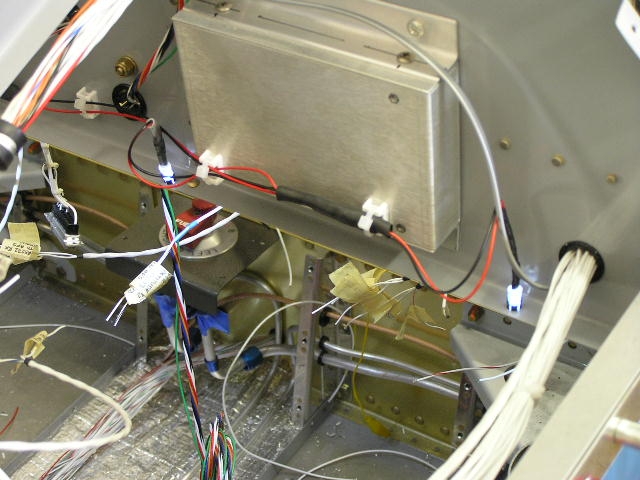 |
4.0 | ||||||||||||||||||
|
TruTrak ADI &
Autopilot Installation |
||||||||||||||||||||
| 8/16/08 | I installed the TruTrak ADI as
well as the DII-VSGV flat pack autopilot controller. I
wired the connector for the ADI and had to cut into the harness
in order to tap a GPS RS-242 out feed. This feed will
drive the directional indicator on the ADI.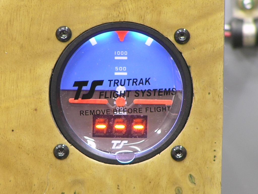 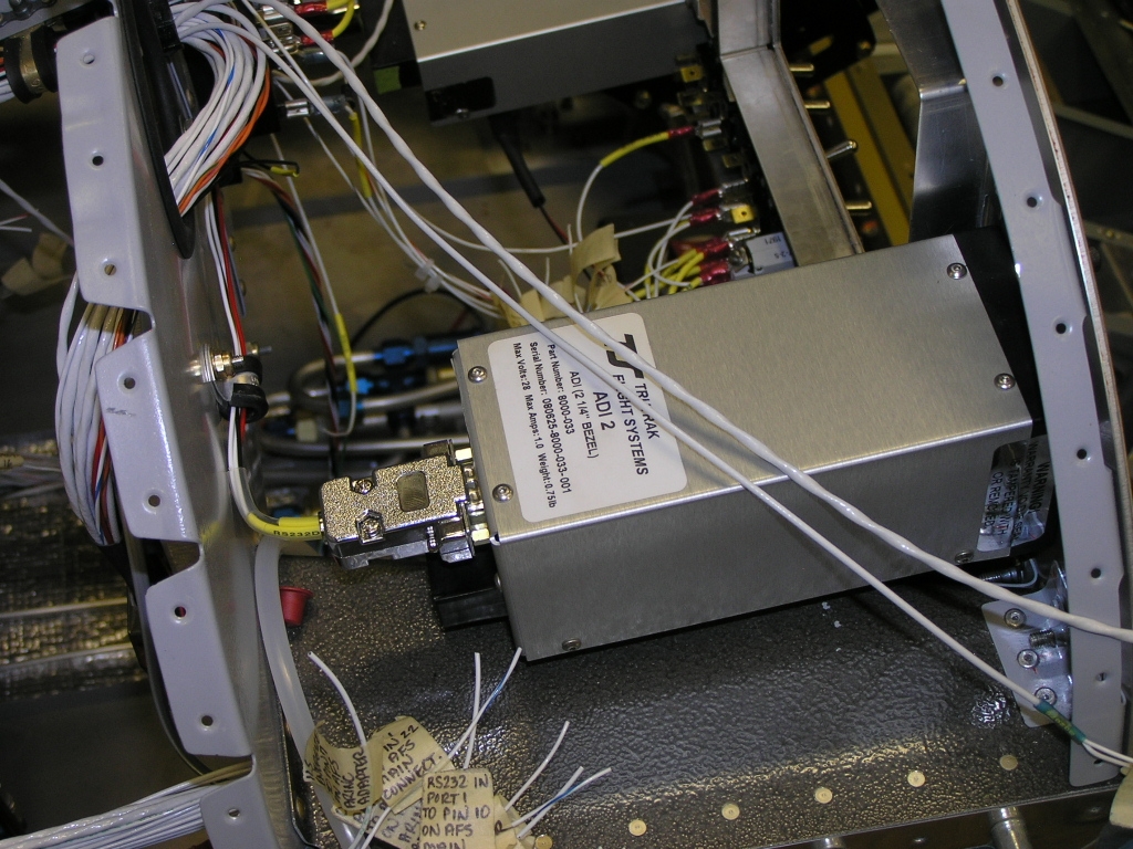 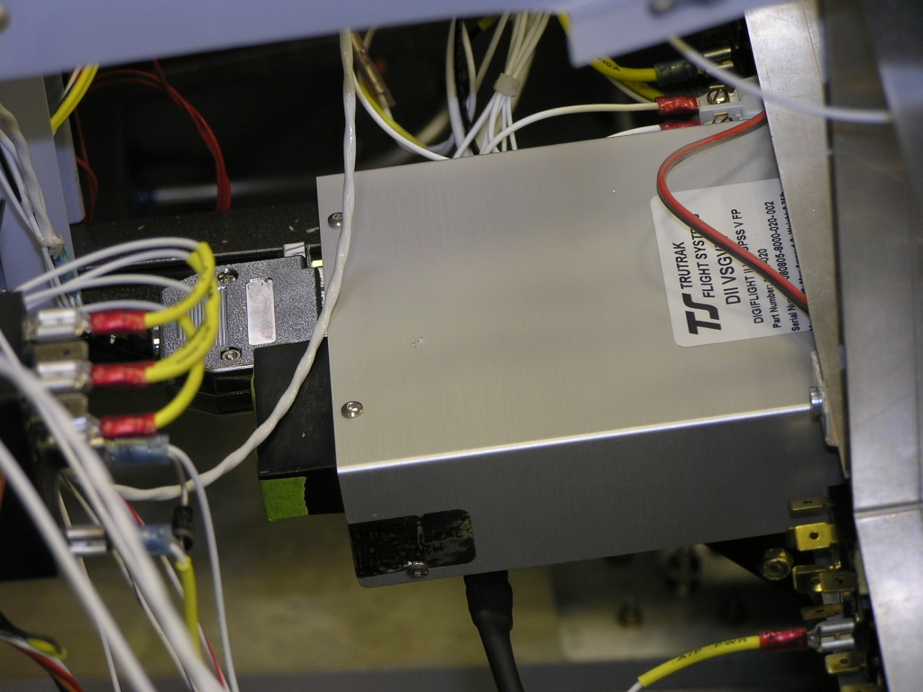 |
3.0 | ||||||||||||||||||
| 8/17/08 | Finished wiring the ADI and
started wiring the main EFIS screen harness.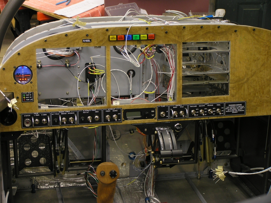 |
3.0
|
||||||||||||||||||
| 8/22/08 | I had a visit from two of our
EAA Chapter members, Jack Ryan and
Chuck Ogle. Both of these
guys heard I was in the middle of wiring so they decided to stop
by and check out my work. Jack is an A&P and Chuck has
over 40 years of avionics experience. Being the consummate
host, I put them both to work soldering my headset jacks.
Thanks guys.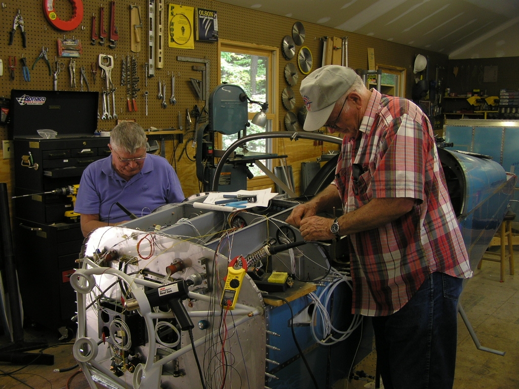 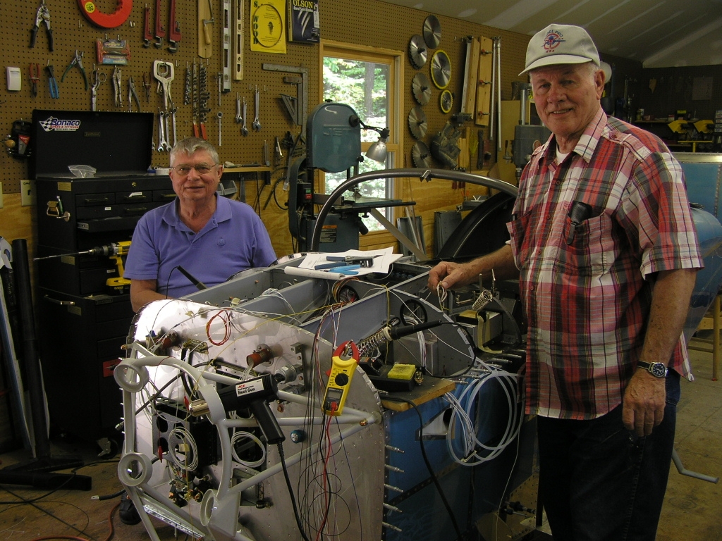 |
4.0 | ||||||||||||||||||
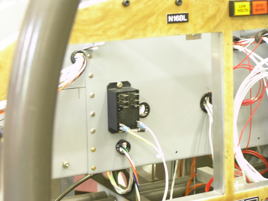
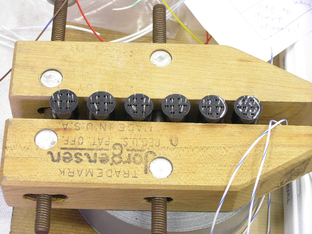
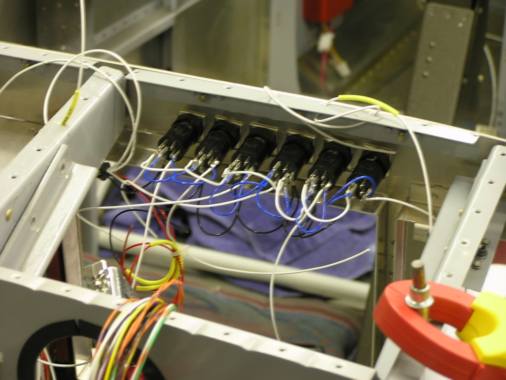
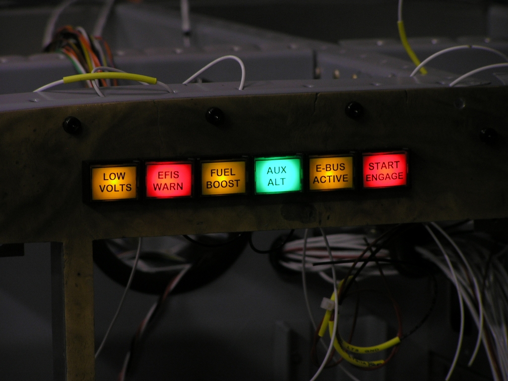
| 8/23/08 | Annunciator
Wiring Today I installed and wired the
engine monitor harness from AFS.
I also took some time and soldered up my annunciator lights.
These lights are actually lighted DPDT switches. With the
help of Mark Phillips, who devised
the wiring schematic, I can press each switch and determine if
the LED is working.
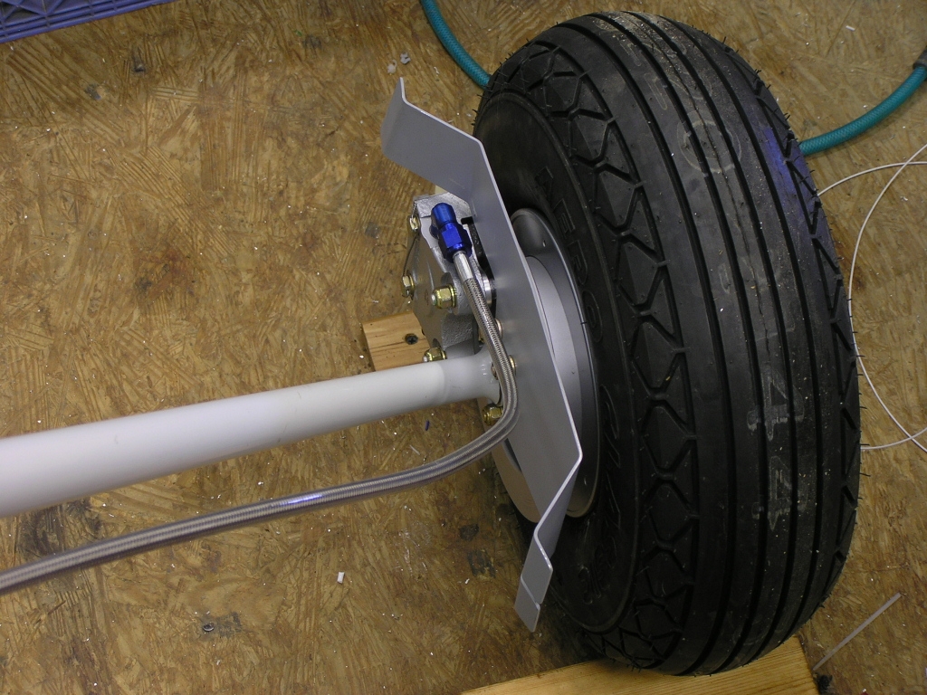
I also started assembling the
landing gear. |
4.0 | ||||||||||||||||||
| 8/30/08 | Today I worked on
finishing the wiring. I had several small things to wrap
up including the EI Capacitance Fuel Senders, the XM Radio, the
RPM sensor wiring as well as about 100 other things. I am
waiting for a patch cable from Stark Avionics which will allow
my EFIS to receive and display traffic from my Garmin 330.
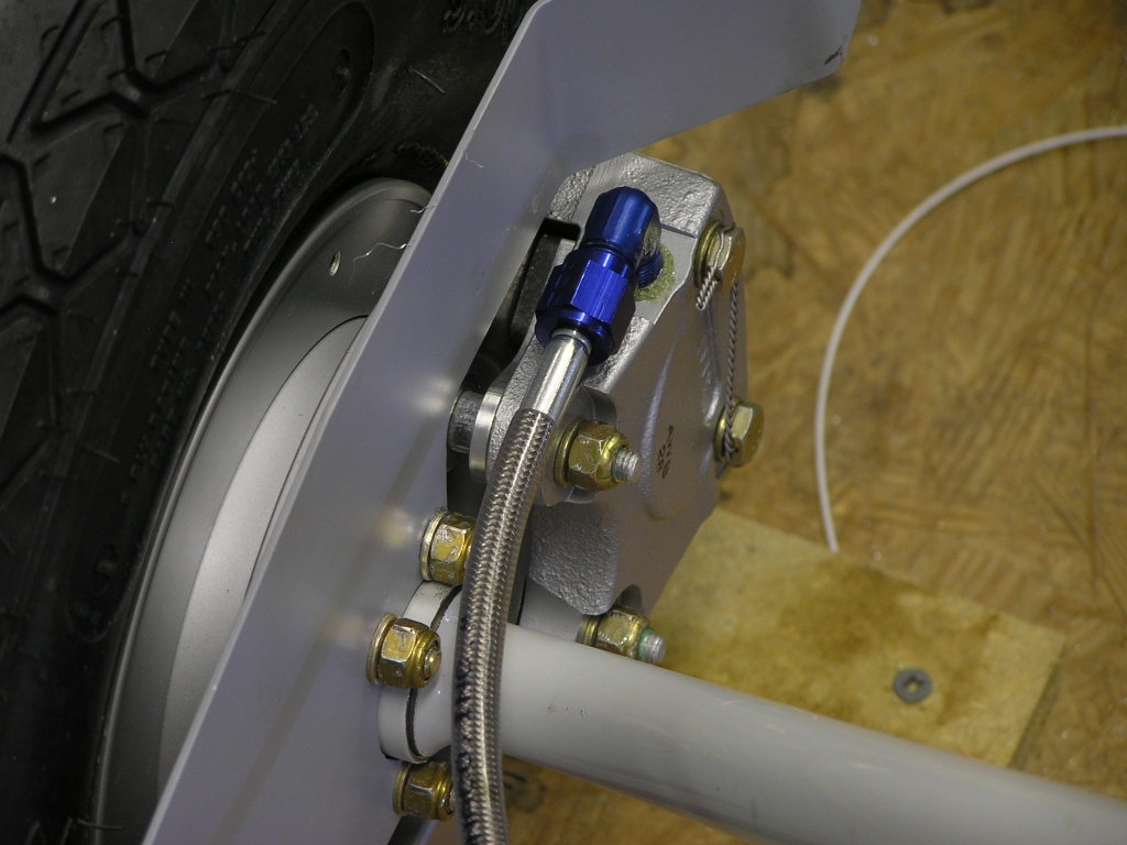
I also received my braided fuel lines from
Brett at
Bonaco. These are the lines that run down the
gear legs. Finally, my neighbor Don, Lynne and I put the
plane up on it's gear! |
6.0 | ||||||||||||||||||
| 8/31/08 | I finished the last few wiring
issues outstanding and even tested a few circuits. I still
need to finish the annunciator lights and need to research the
light wiring a little more. I still need to lace up a few
more wire runs in order to make it look nice. This is the
really tedious part of the wiring. |
5.0 | ||||||||||||||||||
| 9/1/08 | I have all the annunciators
working except the Low Volts and
the main EFIS Warn. I
continued to work on lace tying the wire into bundles.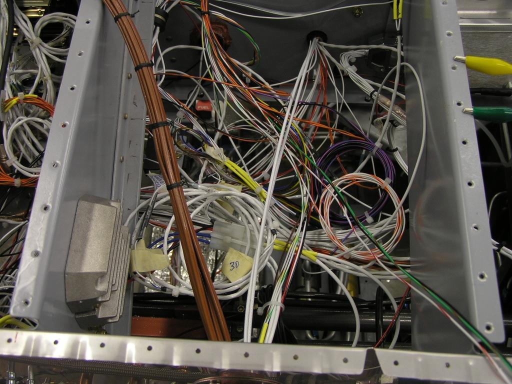 |
4.0 | ||||||||||||||||||
| 9/27/08 | Labeled the fuse panel.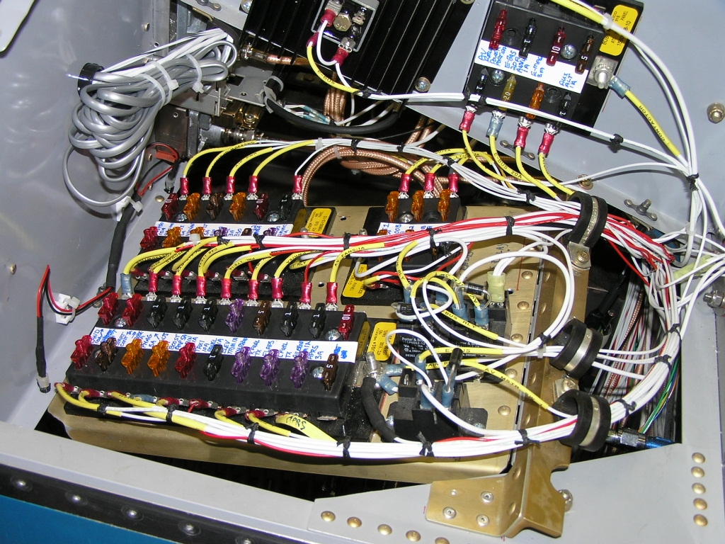 |
.5 | ||||||||||||||||||
|
Total Hours this Page |
||||||||||||||||||||
|
Total Hours Wiring |


Copyright ©2005-09
Hosted by NTI Networks