
Home
Shop
Tools
Empennage
Wings
Wings 2
Wings 3
Wings 4
Flaps
Pushrods
Riveting Bottom Skins
Gretz Pitot Install
Wing
Wiring
HID Light Install
Wingtip Hinge Install
Fuselage
Panel
Firewall Forward
Canopy
Wiring
Miscellaneous
Wings 4
| Flaps | ||
| 2/22/07 | I started by edge deburring the flap components
and clecoed the leading edge attachment assemblies. I then
match drilled and clecoed to the spars.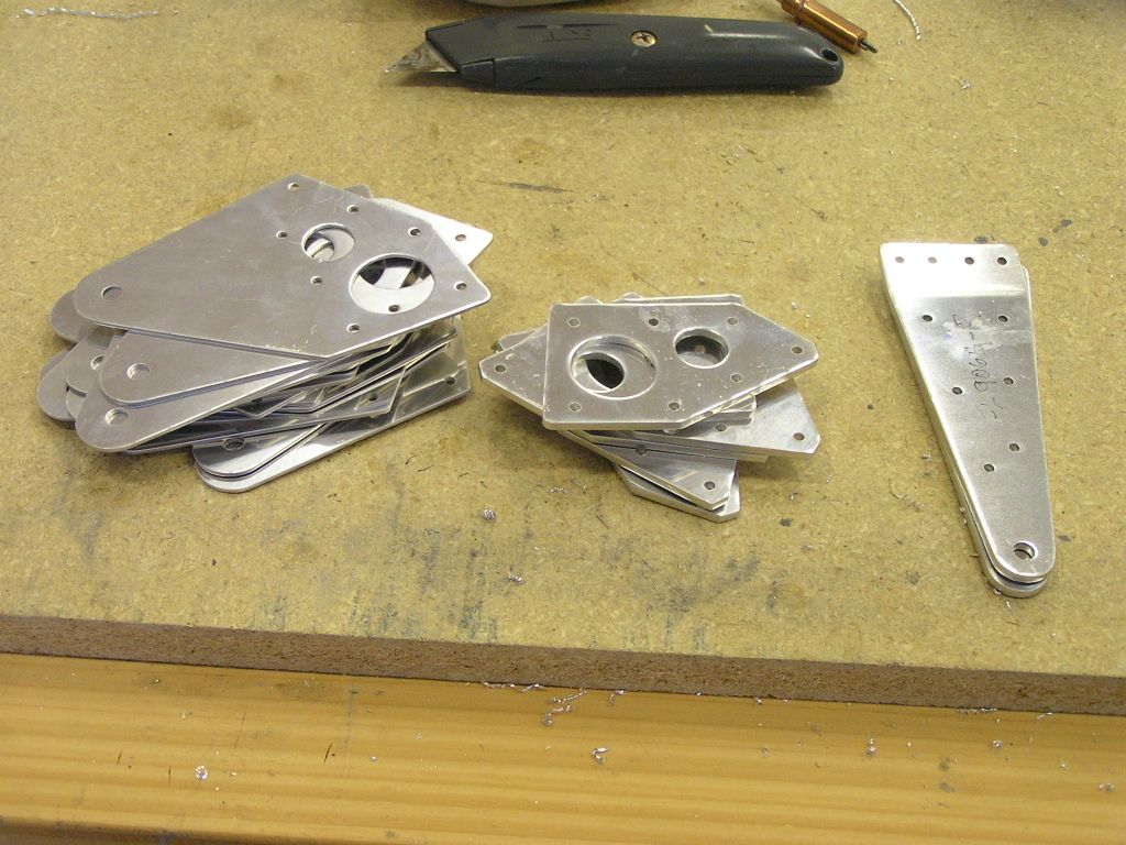 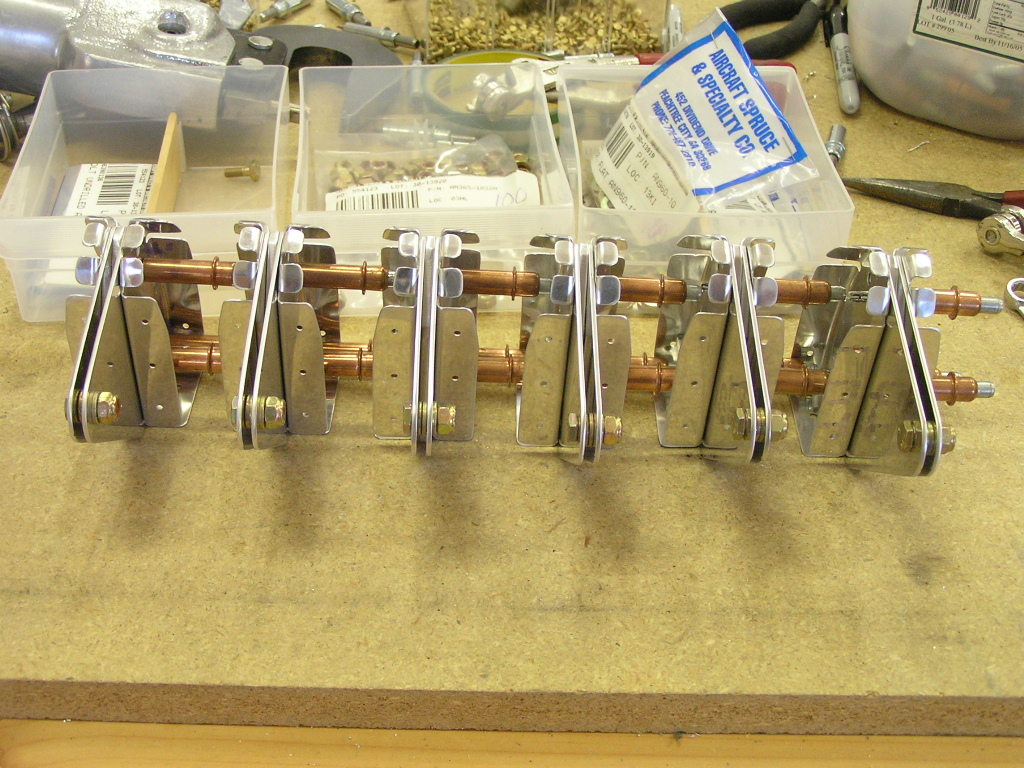 |
4.0 |
| 2/25/07 | Fabricated the 608A brackets as well as the 608C
spacer.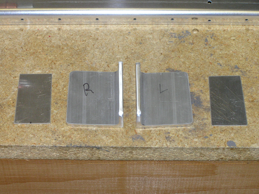
Clamped the bracket and spacer to the spar and back-drilled using the
spar holes as a guide.
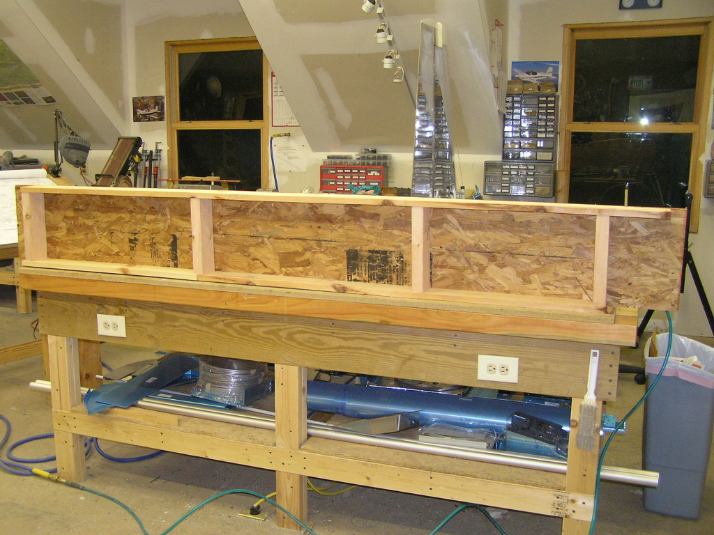
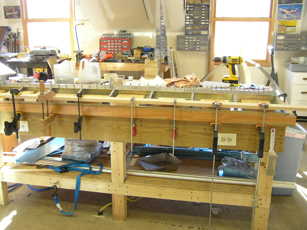
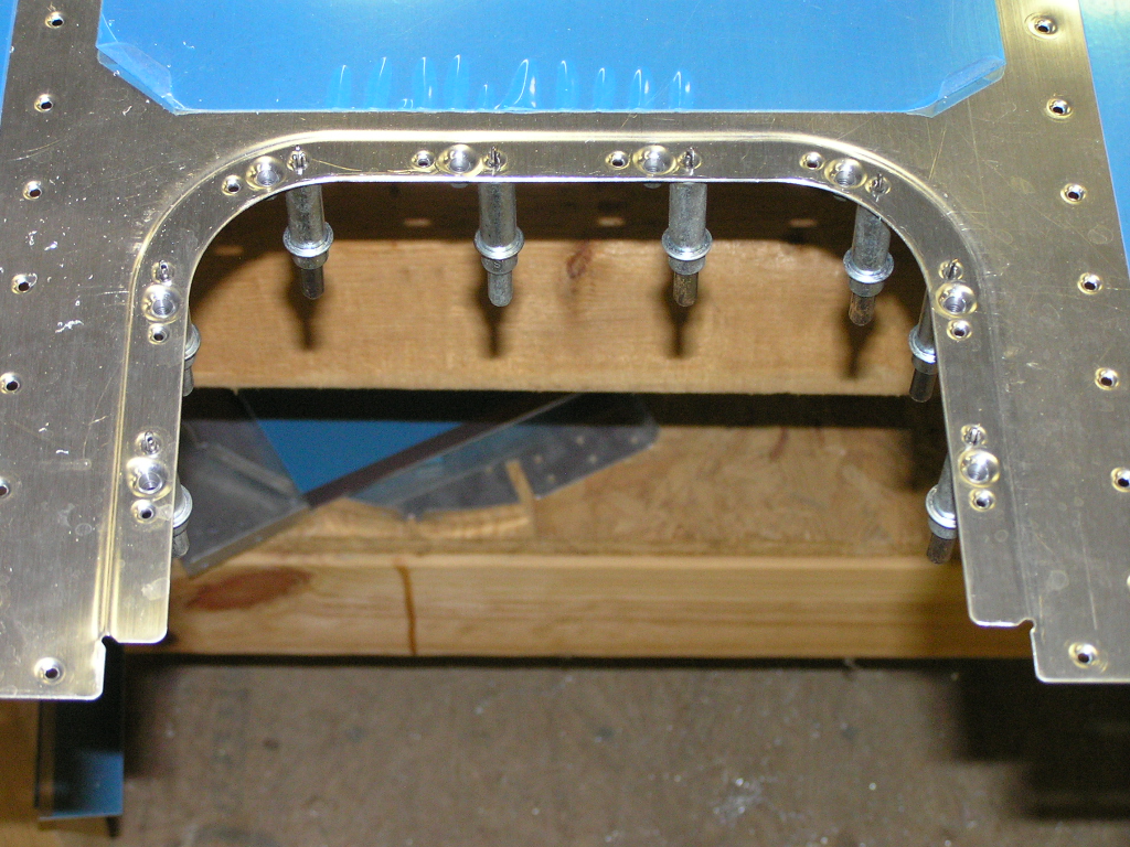
The plans call fr drilling 5/8" holes in the top of your table and
since I didn't want to do that, I decided to build a
"sacrificial" table top. I ripped a 12" x 8' piece of
plywood and built a frame out of 2x4's and 1x4's. After
securing the top to the frame I have a top that I can throw away
once the flaps are complete.
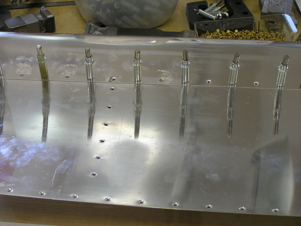
I clecoed the bottom skin to the left flap spar and then drilled
through the bottom skin into the top of the sacrificial table. |
|
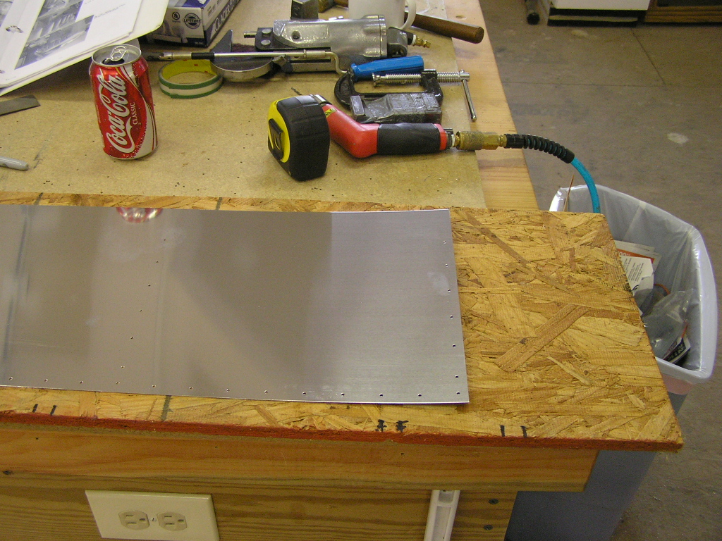
| 3/3/07 | I removed the flap skin and drilled out the
cleco holes to 1/2" so the clecos will fall below the table
allowing the skin to lay flat.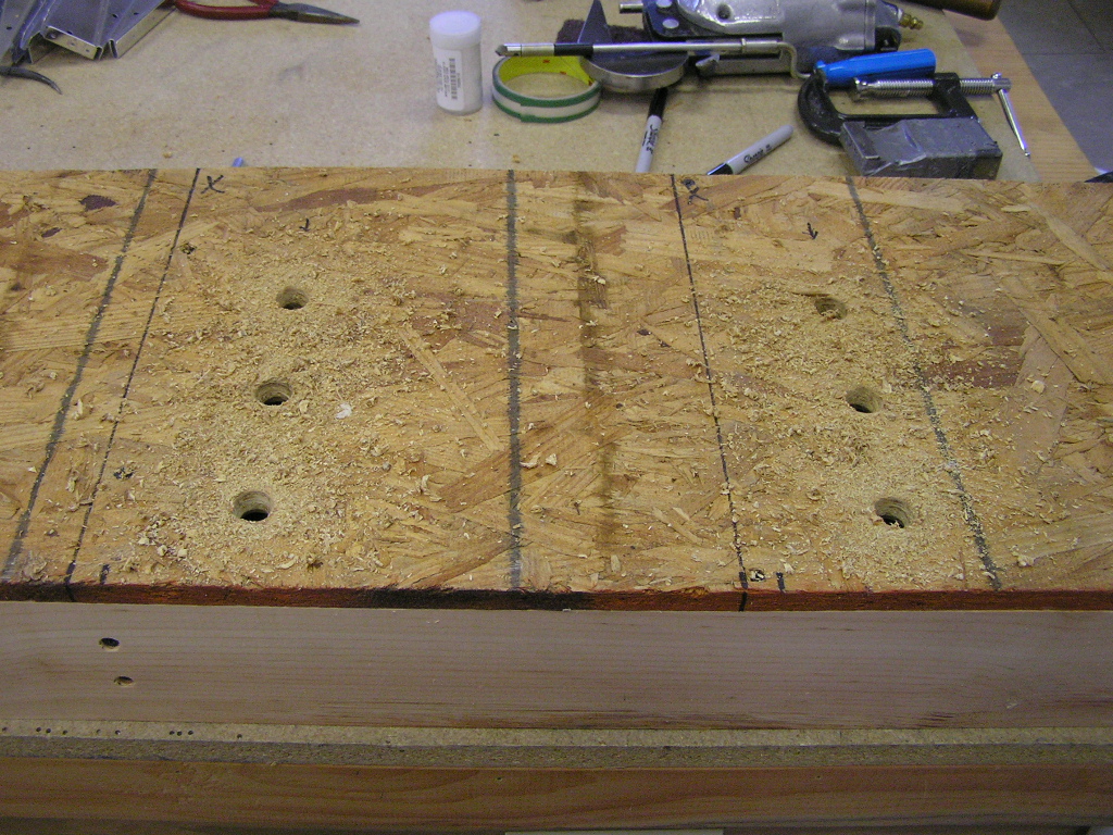
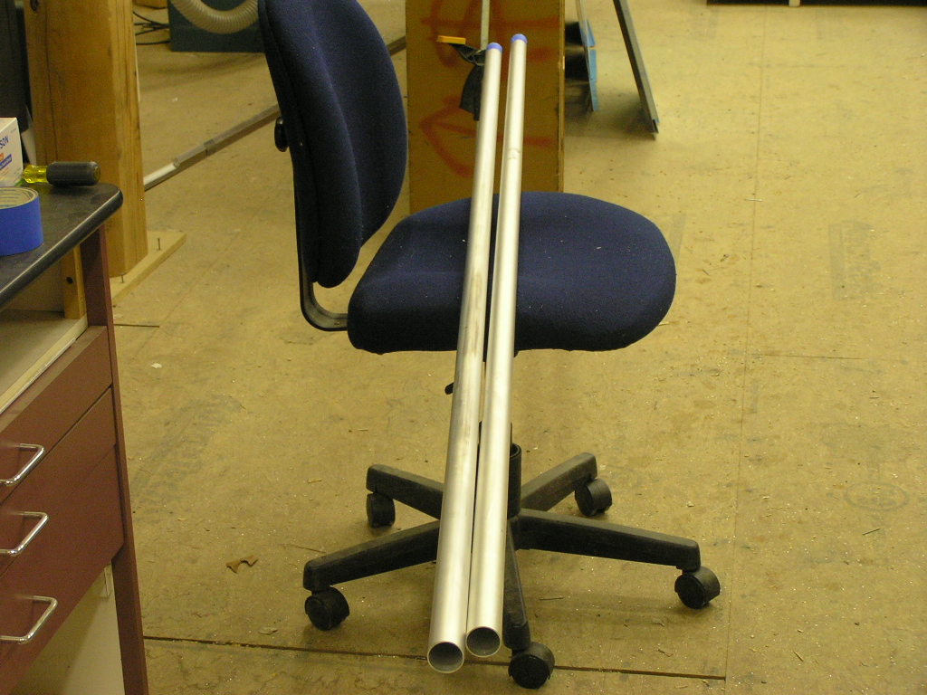
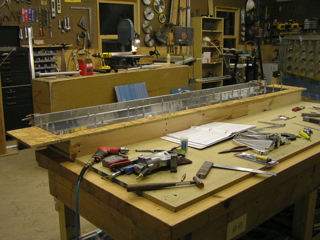
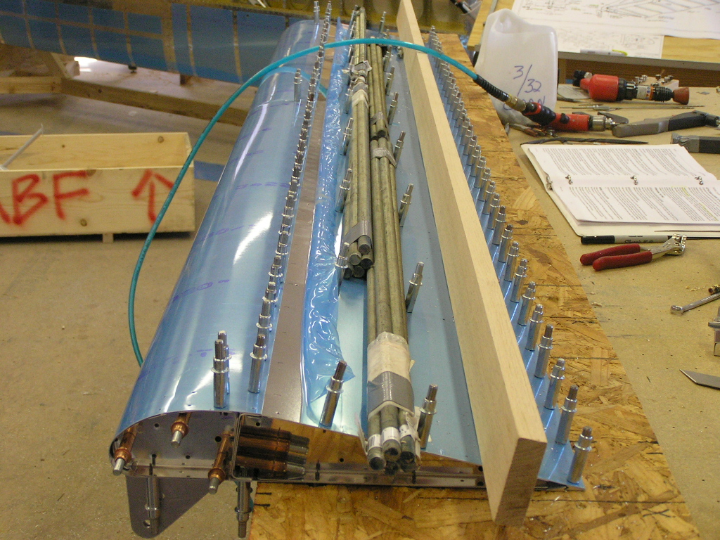
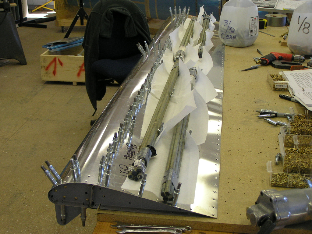
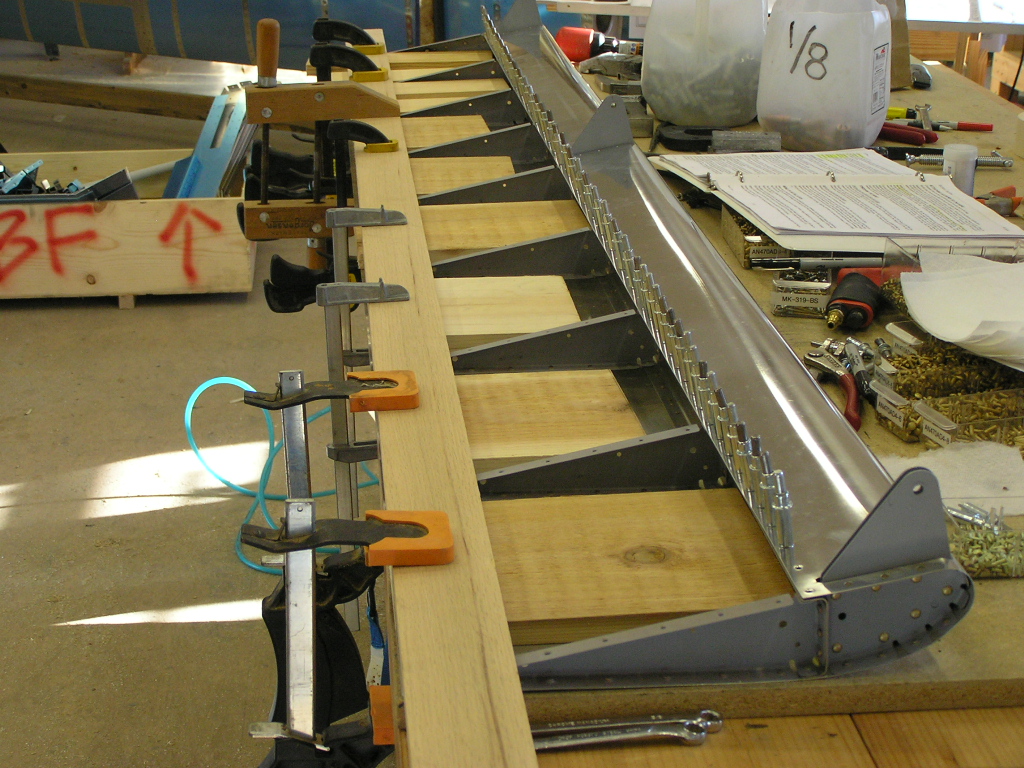
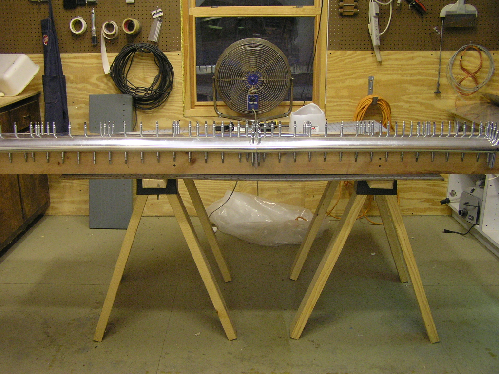
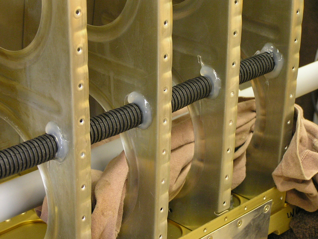
I assembled the left flap by clecoing the ribs to the spar,
skins to ribs and leading edge skin to spar. I weighed the
flap assembly down with some threaded rods I had laying around.
I taped them together and each bundle weighed approximately 5
lbs. each. Inserted
trailing edge AEX wedge and drilled trailing edge. Match
drilled all holes. Disassembled flap components and deburred. Drilled K1000-4
platenut to inboard rib and bracket and countersunk. Dimpled ribs and countersunk spar. Deburred bottom skin. |
10.0 |
| 3/4/07 | Deburred top left flap skin. Assembled
right flap by clecoing ribs to spar,
skins to ribs and leading edge skin to spar. Inserted
trailing edge AEX wedge and drilled trailing edge. Match
drilled all holes except inboard flap attach bracket.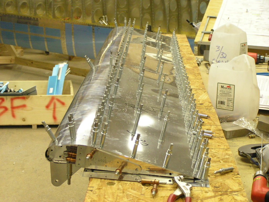 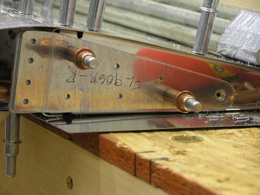
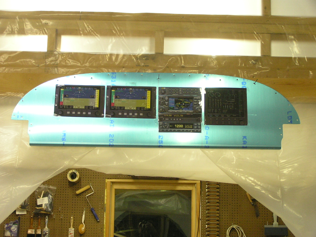
I decided to print out some true size photos of the avionics I
plan to use and start a "mock up" panel. Over the next few
months I will be able to look at it and see how it fits. |
4.0 |
| 3/9/07 | Drilled inboard flap attach
bracket and drilled platenut. Disassembled right flap
assembly and deburred leading edge ribs and main ribs, leading
edge skin and spar. |
2.0 |
| 3/10/07 | Countersunk spar and trailing
edge AEX wedge. Deburred left and right flap skins and
dimpled. Dimpled ribs. Scuffed left flap ribs and
leading edge components with dishwashing liquid. |
6.0 |
| 3/11/07 | Scuffed right flap components
with dishwashing liquid.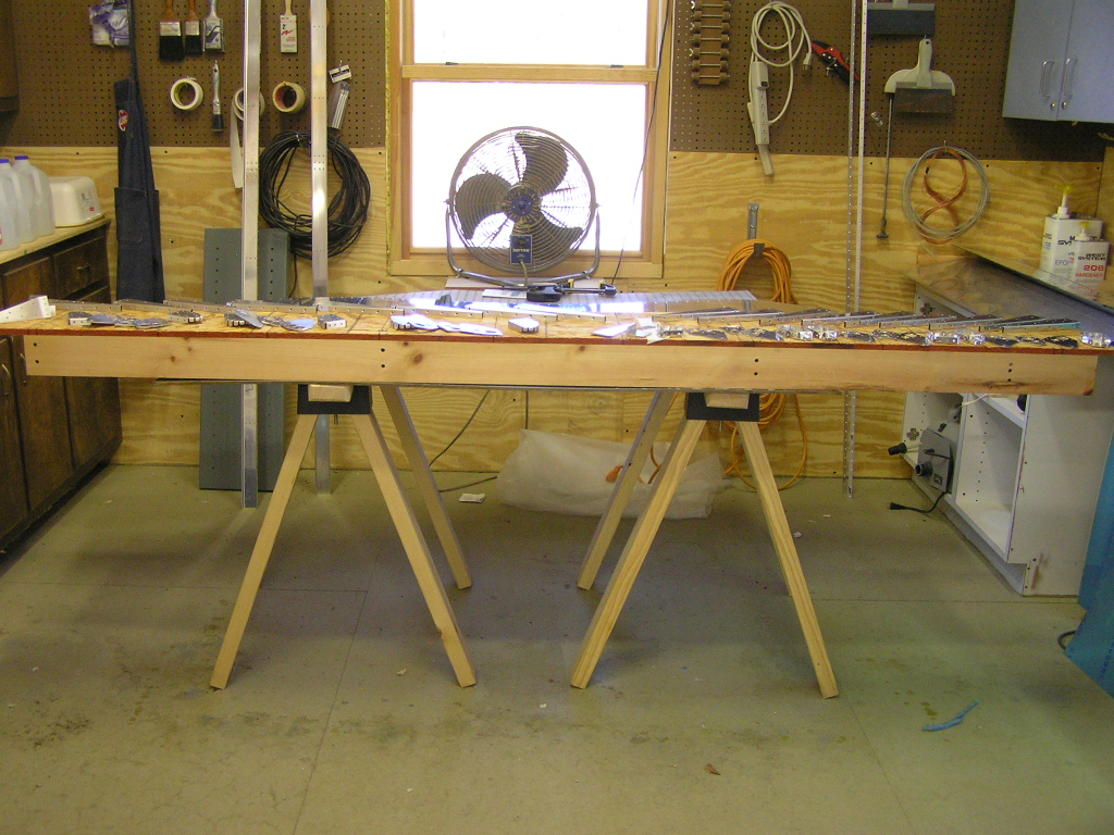 |
1.0 |
| 3/13/07 | Alodined ribs and flap bracket
components. Sanchemed spars and AEX wedges. |
1.5 |
| 3/14/07 | Scuffed top and bottom skins for
both flaps with soapy water. Dimpled leading edge skins
for left flap. |
1.0 |
| 3/17/07 | Finished priming the flap
components. I decided to alodine the ribs and leading edge
hinge brackets and then sprayed with self-etching primer.
I used SanChem for the inside skins and leading edge skins. |
3.0 |
| 3/18/07 | Riveted the leading edge brackets
for both flaps and riveted them to the spars. Riveted the
remaining ribs to the spars.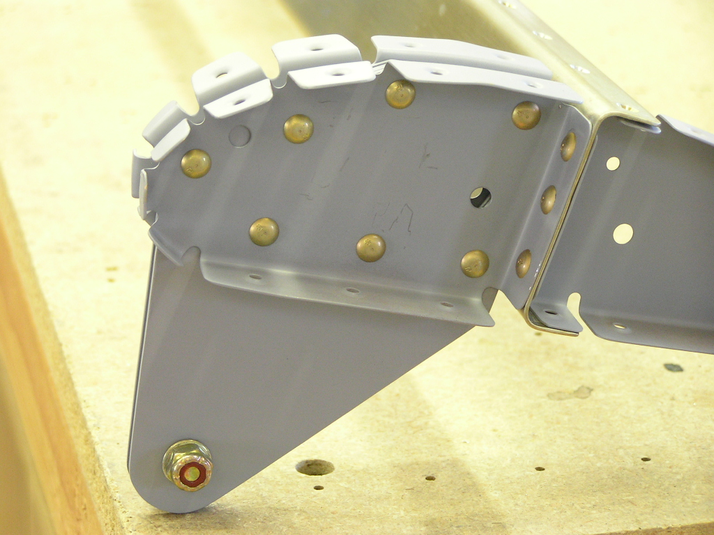 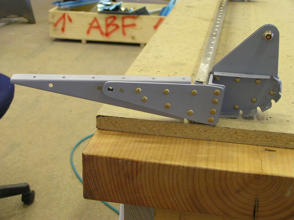 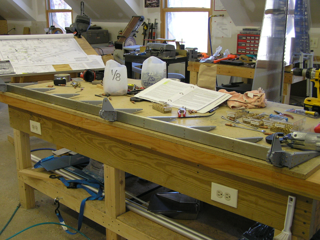
Clecoed the top skin and leading edge skin to the
left flap and riveted. Flipped the left flap over devised a way to
weigh down the skins. I found some 1x10's and clamped them
to the table. It works really well. I then clecoed the bottom skin and started
riveting the bottom skin and leading edge skins to the spar. |
7.0 |
| 3/21/07 | Finished riveting the bottom skin and leading
edge skins to the spar. BTW, I used -4 length rivets
because I didn't seem to get large enough heads using the -3.5's
called out in the plans. I then drilled the bottom skin to
the ribs to 7/16 and installed the blind rivets. |
2.0 |
| 3/22/07 | I decided to use proseal on the trailing edge
AEX wedge. I mixed about 2.2 ozs. per my scale and applied
a thin coat to both sides. After inserting the wedge I
clecoed every hole and left to set up.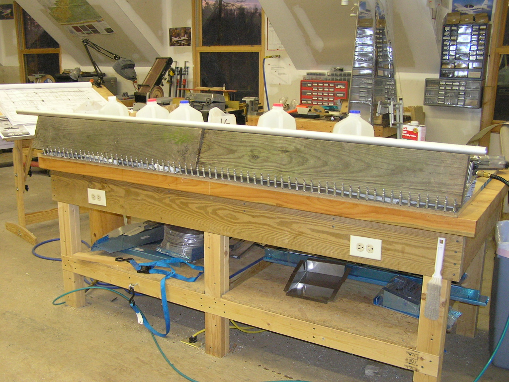
I clecoed the top skin and leading edge skins to the spar and
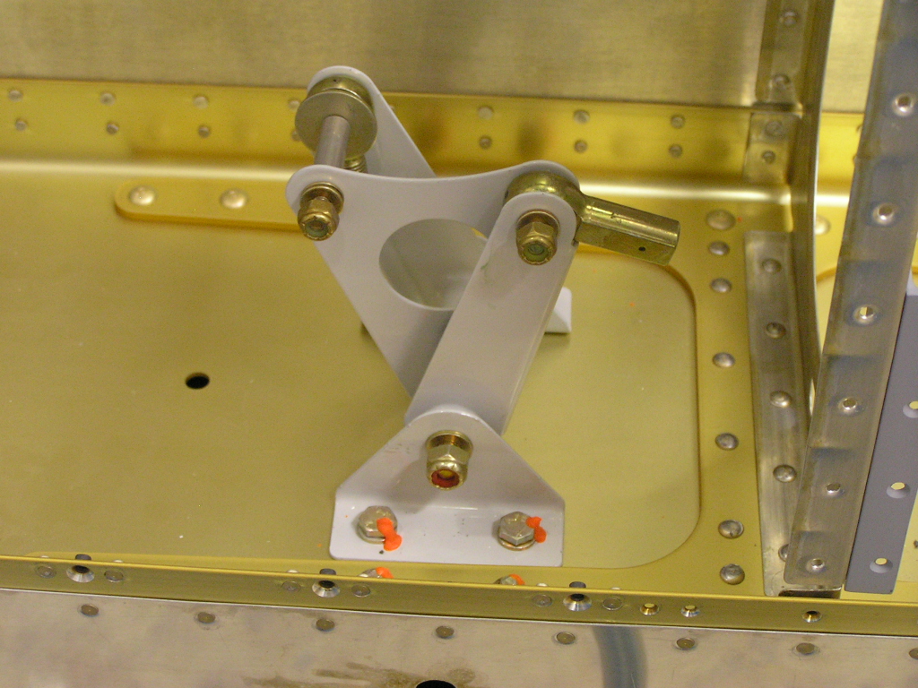
ribs of the right flap. I worked on the left wing aileron bellcrank by reaming the
brass bushing for the bolt. I also had to ream the
bellcrank in order for the bushing to turn smoothly. I
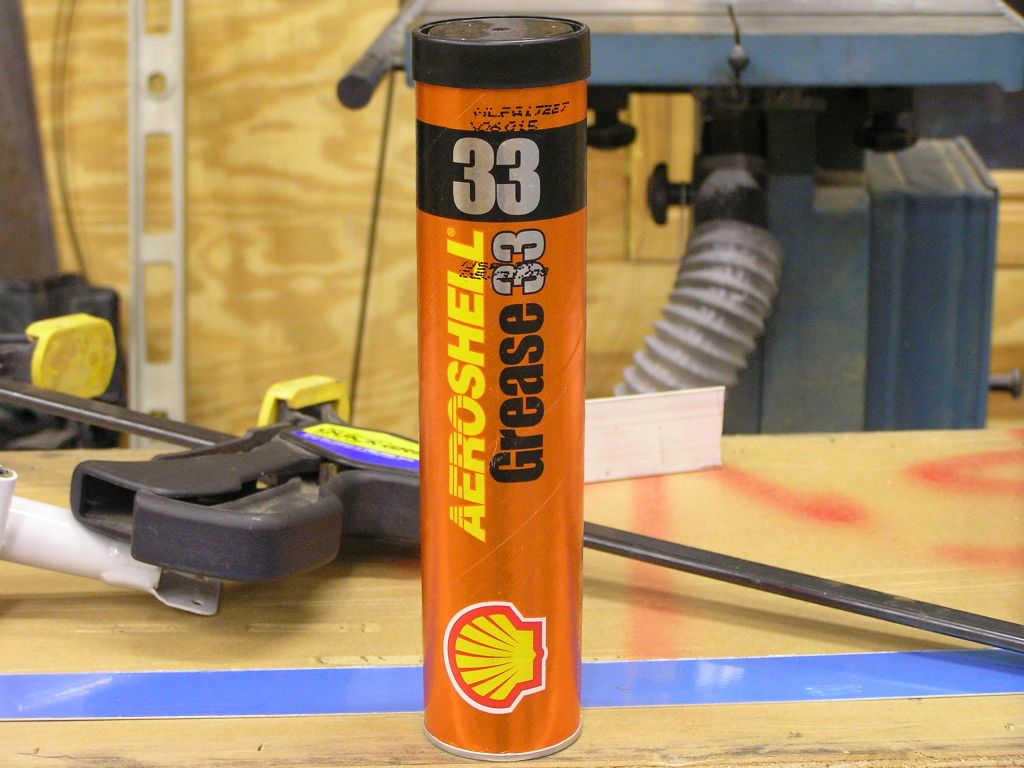
decided that "my favorite grease" (inside joke) is Aeroshell 33.
I greased the bushings in both bellcranks and installed. I'm ready to construct my aileron pushrods but need to verify
that the pushrod lengths specified in the plans is correct. |
3.0 |
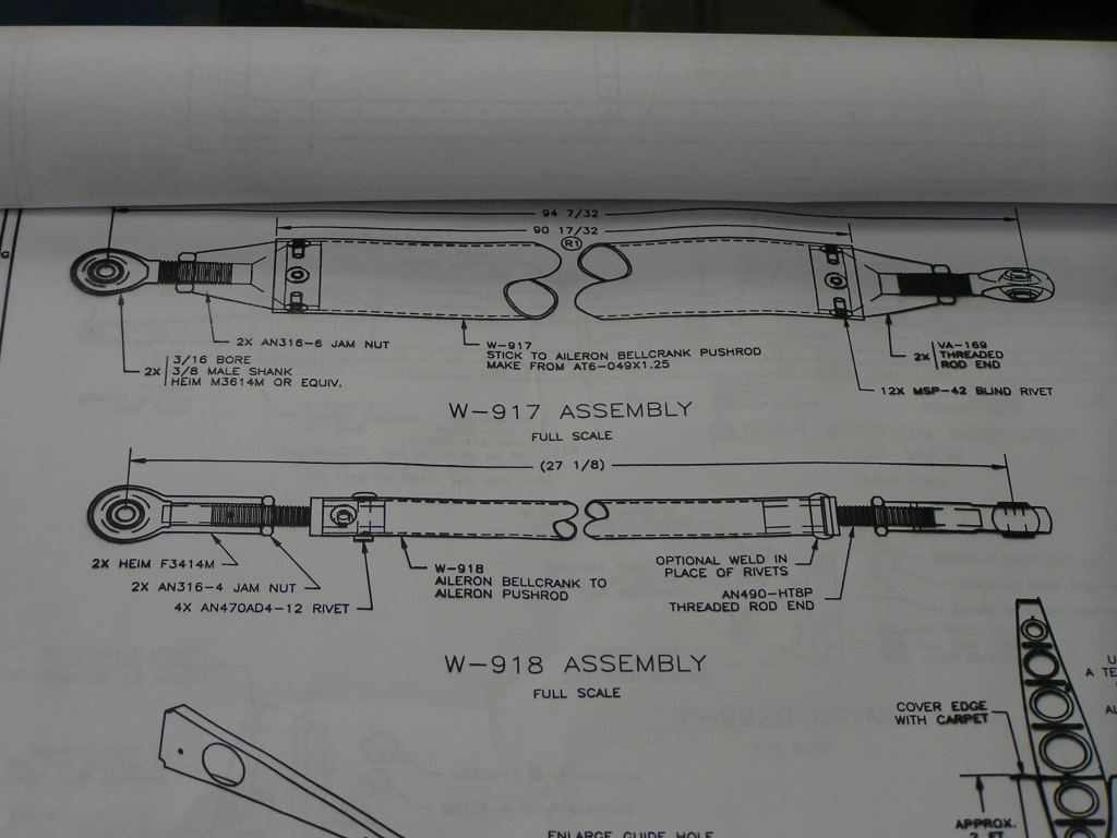
| 3/23/07 | I called Van's Technical Support and was told
the lengths specified in the plans are correct. Cut the
W-917 stick to aileron bellcrank pushrods 90 17/32".
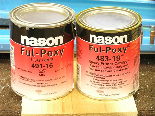
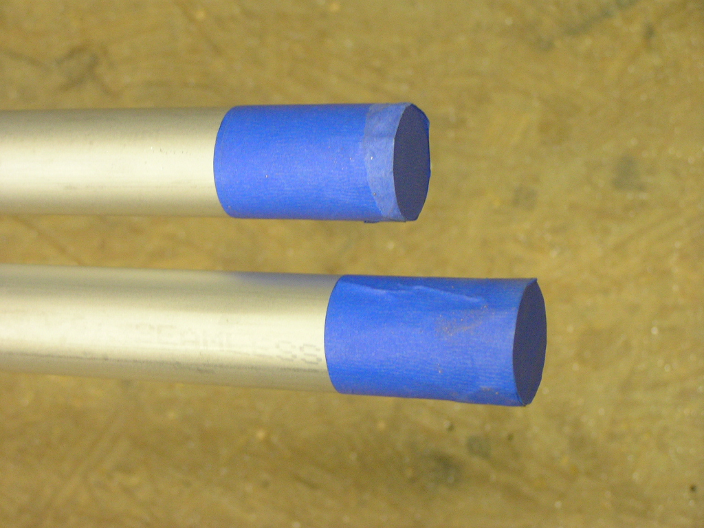
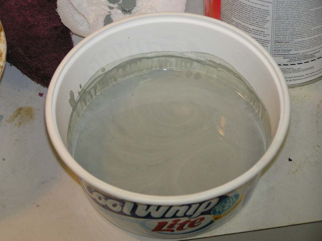
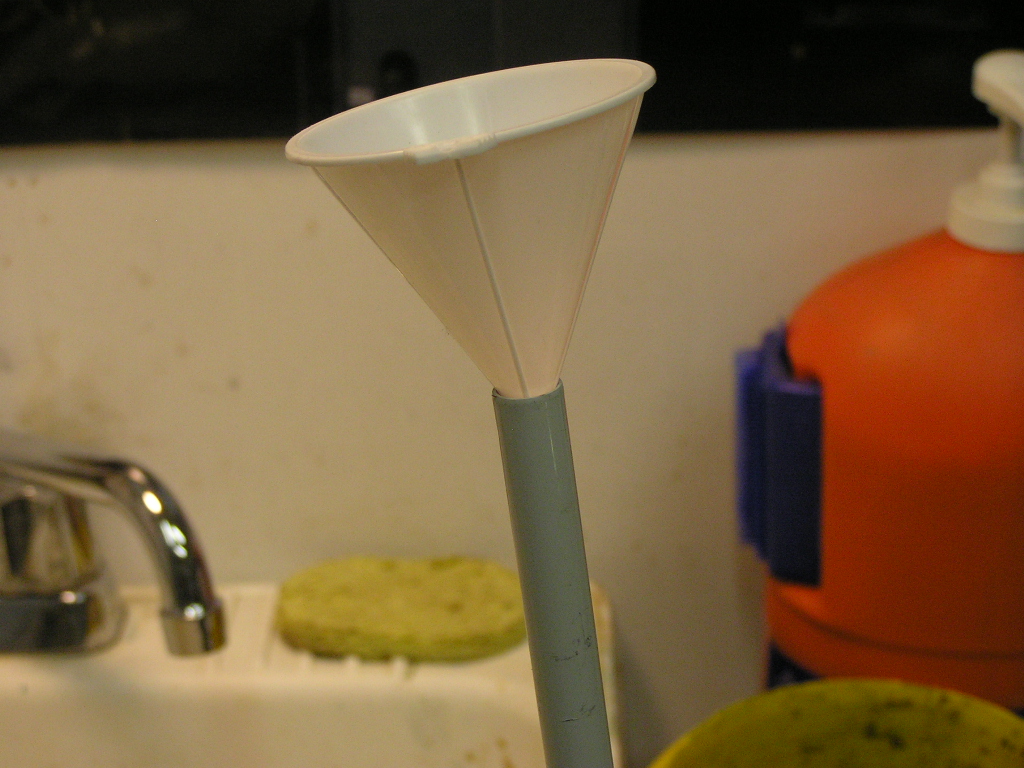
 After
deburring I taped one end of each tube and mixed up some primer.
For this purpose I am using Nason 2-part self-etching epoxy primer.
I poured the primer inside each tube and coated the inside
thoroughly. I also primed the inside of the W-918 aileron
bellcrank to aileron pushrod. Finally, I used rattle can
self-etching primer to spray the outside of the two W-917 tubes. |
2.0 |
| 3/24/07 | I cut the W-918 aileron bellcrank to aileron
pushrod ~27". I am going to have the ends welded as
opposed to riveting. There have been reports of the rivets
"catching" on the edge of the hole where the pushrod passes
through the rear wing spar and I don't want to enlarge the hole.
I sanded the ends where they will be welded to remove the powder
coating.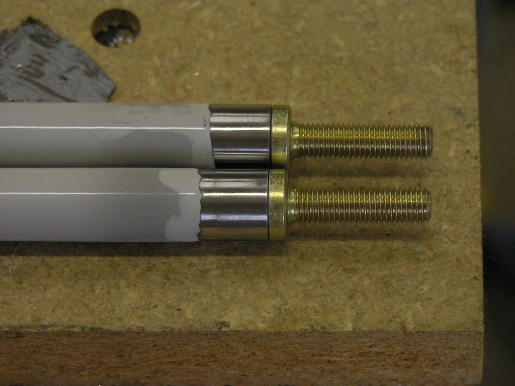 Back to the flaps. I removed the weights from the flap and
removed the clecos in the trailing edge. It was soon
apparent that two days was insufficient for the ProSeal to
adequately cure and bond the trailing edge. I had to get
creative in order to hold it all together long enough to insert
the rivets in the top and tape them in place for back-riveting. I flipped the flap top-side down and used my heavy angle as a
back-riveting plate. I used 3/16" foam sheets as a leveler
for the rest of the flap. I half-shot the rivets and
flipped the flap over. I used the mushroom set to finish
the riveting. I again used -3.5 rivets instead of -3
rivets called out in the Plans in order to get a sufficient shop
head. The left flap is done and perfectly straight! I started again on the assembly of the right flap by drilling
the leading edge skin to 7/64" and blind riveted all but the
outside edges where I squeezed solid rivets. I then shot
the majority of leading edge skin to top skin to spar rivets.
Here, again, I prefer to use -4 rivets as opposed to the -3.5
rivets called out in the Plans in order to get a sufficient shop
head. |
5.0 |
| 3/25/07 | Finished shooting the leading edge skin to top
skin to spar rivets. Riveted the top skin to ribs.
After flipping the flap over and "clamping" the top skin to the
table I riveted the majority of leading edge to bottom skin to
spar rivets. This clamping technique holds the flap
perfectly flat to the table and allows moderately
unobstructed access to the spar for bucking. The word
for today is "tedious".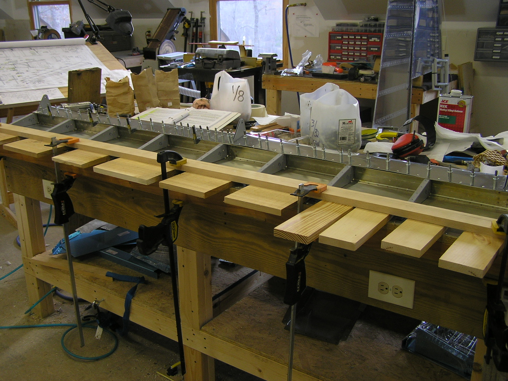 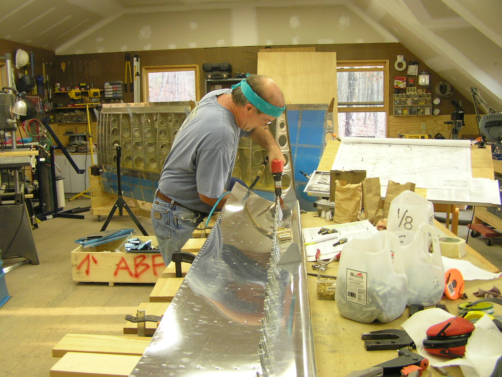 |
2.0 |
| 3/26/07 | Finished riveting the leading edge to bottom
skin to spar rivets. Installed the blind rivets in the
bottom skin to ribs and squeezed solid rivets in the end rib.
I wasn't happy with the way the ProSeal worked on the trailing
edge on the left flap so I decided to use T-88 on this one.
I've been really happy with how well the T-88 bonded the
trailing edges on the rudder, elevators and ailerons.
Ron Russ gave me a good tip on how to heat the T-88 in a pan
of hot water to make it "soften" and flow more easily. I
put clecos in every hole of the trailing edge. Now to let
the trailing edge set up.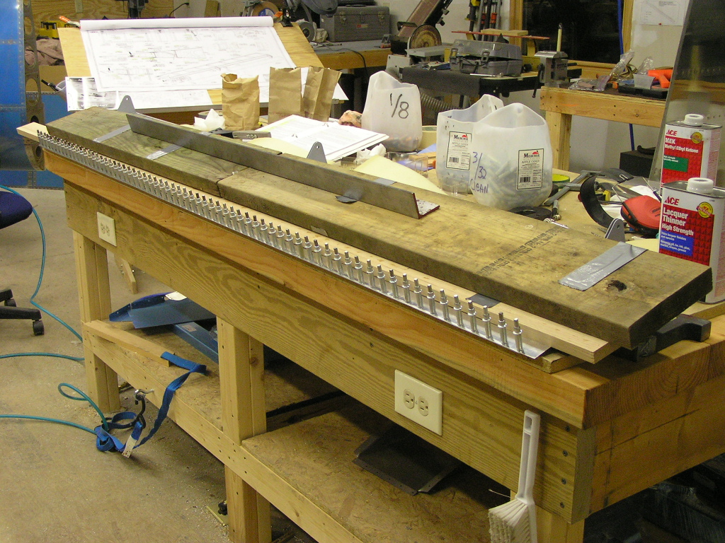 |
2.0 |
| 3/27/07 | Tonight I removed the clecos in the trailing
edge and taped in the -3.5 rivets on the topside. After
flipping the flap topside-down, I half-shot the rivets and
flipped the flap over. I used the mushroom set to finish
the riveting. I again used -3.5 rivets instead of -3
rivets called out in the Plans in order to get a sufficient shop
head. The right flap is done and perfectly straight!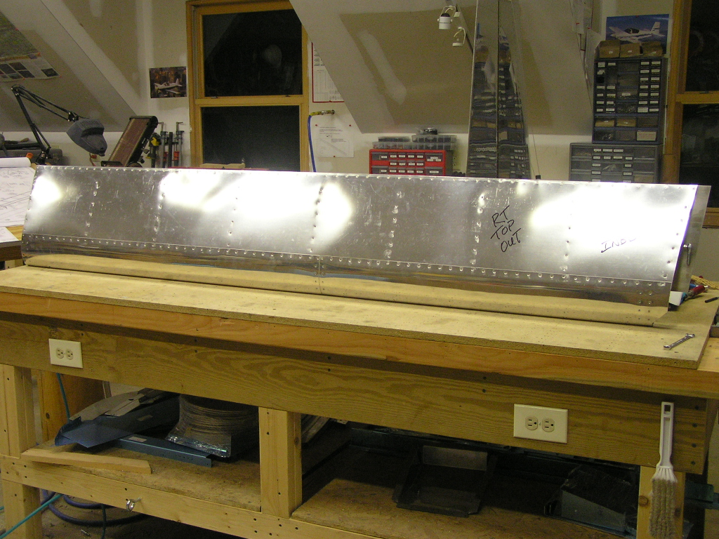 |
2.0 |
|
Total Hours Flaps |
57.5 | |
| Bellcranks and Pushrods | ||
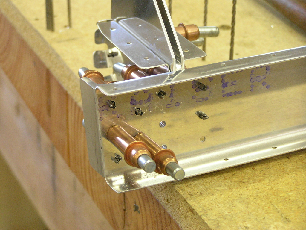
| 3/28/07 | Laid out a design to drill the rivets
equidistant. Marked the pushrods and drilled the holes to
#30. Deburred the holes and inserted the pushrod ends.
Match-drilled the pushrod ends and inserted the blind rivets.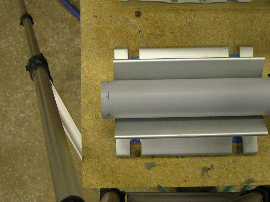 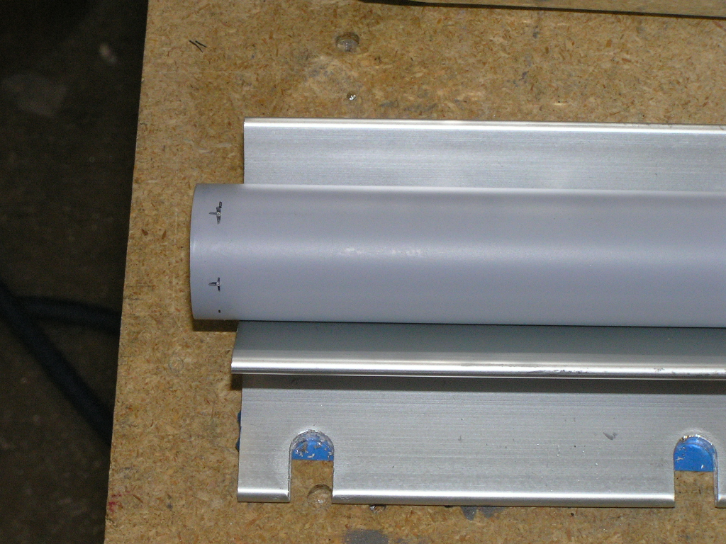 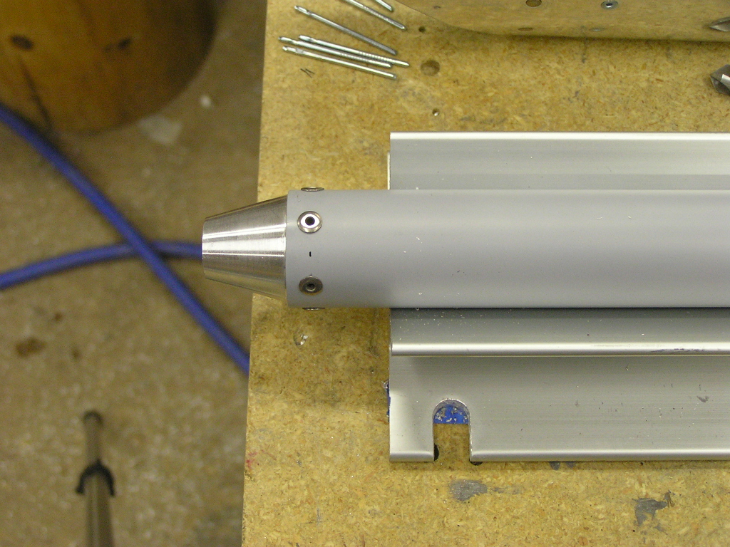 |
1.0 |
| 3/30/07 | Installed pushrods to aileron bell cranks.
Installed flaps and ailerons to wings. 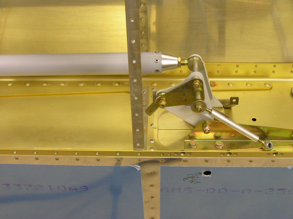 Pulled the Van's
corrugated conduit through the right wing. This proved to
be quite a task and took me almost 30 minutes for just one
wing...I will pull the left wing later. |
2.0 |
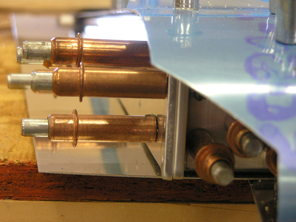
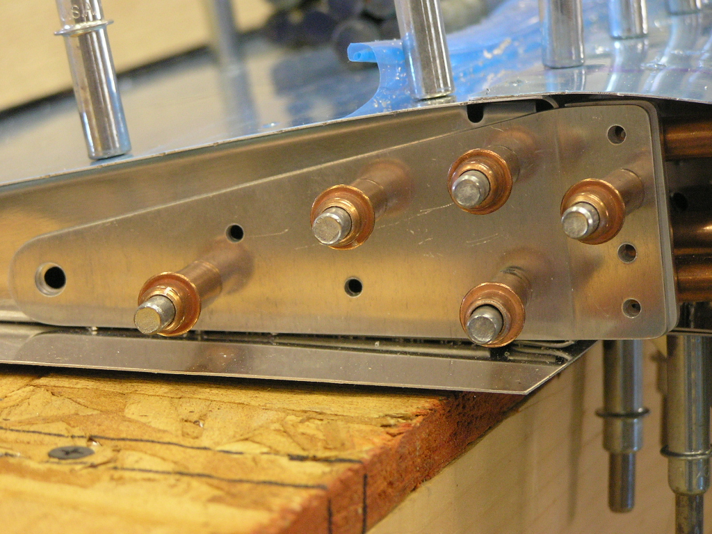
| 3/31/07 | Today I took my bell crank to aileron rods and
rod ends to a local welder. I am really pleased how they
turned out. For those who are interested, the rods are
4130 steel and the rod ends are alloy steel. They can be
welded nicely with a MIG welder using stainless steel wire on
about 30 amps heat. I then ground down the welds and
primed.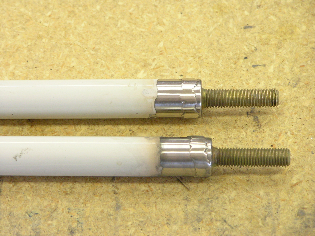
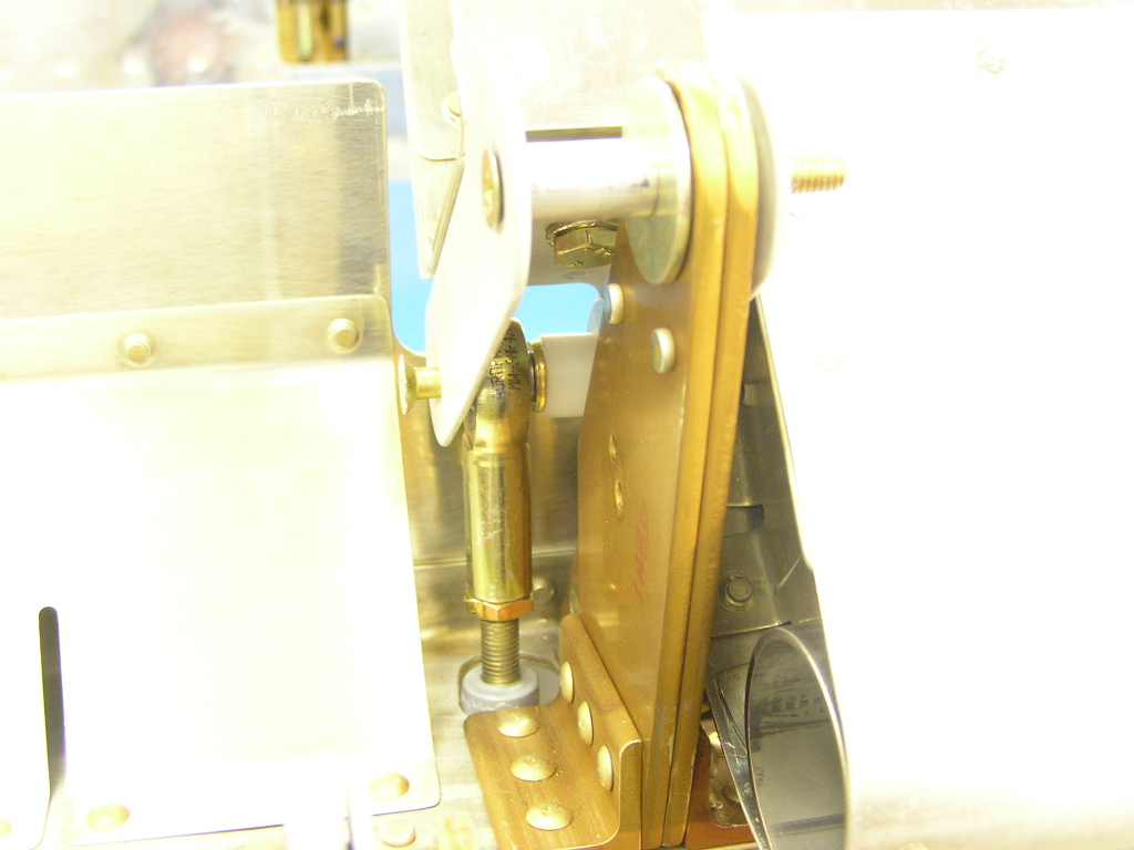
I went ahead and bolted the alignment tool to the end rib on
each wing and clamped the ailerons in the neutral position.
I adjusted the rod-end bearings and bolted temporarily. I
had read where some builders are using delrin rod on the bolt as
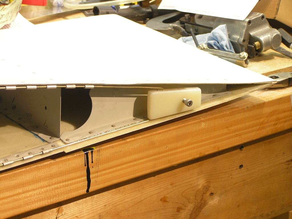
a rudder stop and I did the same. Unfortunately, I was
following the advice of other builders on the VAF Forum and
mistakenly used 1/2" delrin rod. The result (as shown
below) shows the 1/2" rod diameter is too small to hit the
aileron bracket. After re-reading the Forum it appears the
-9 requires a .75" diameter rod. Oh well, another order
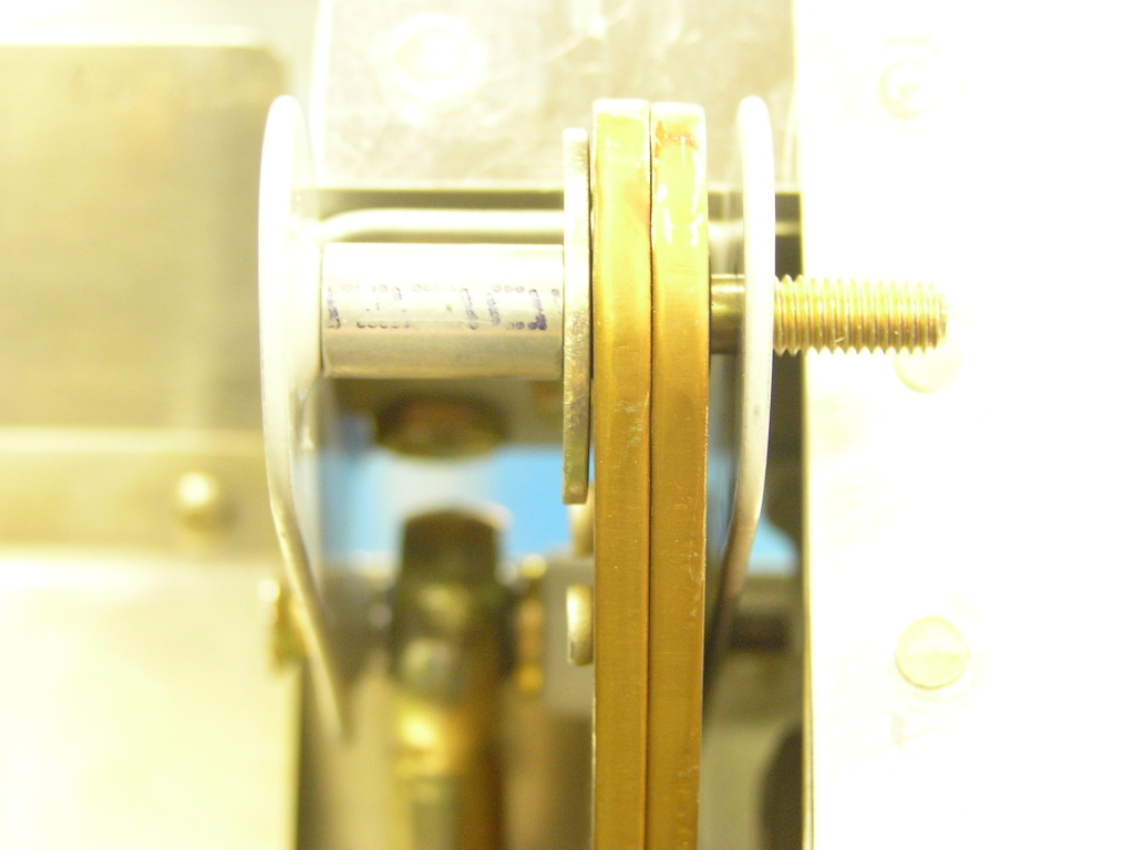
has been placed to ACS... I am a little baffled how to install the washer on this
aileron hinge...It is supposed to go to the right of the bracket
in the "gap" before the hinge. I am embarrassed
to say how much time I have spent trying to figure it out.
I shot an email out to another -9 builder to see what others
have done.
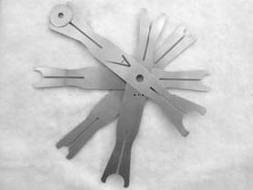
UPDATE: Fellow builder, Bill Repucci, recommended
some thin-walled washer wrenches specially designed for this
purpose so I placed an order to
Avery Tools. |
4.0 |
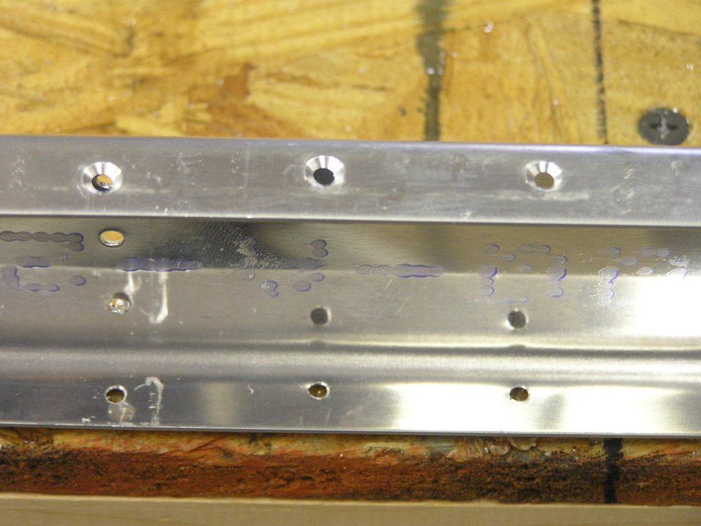
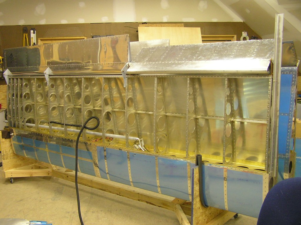
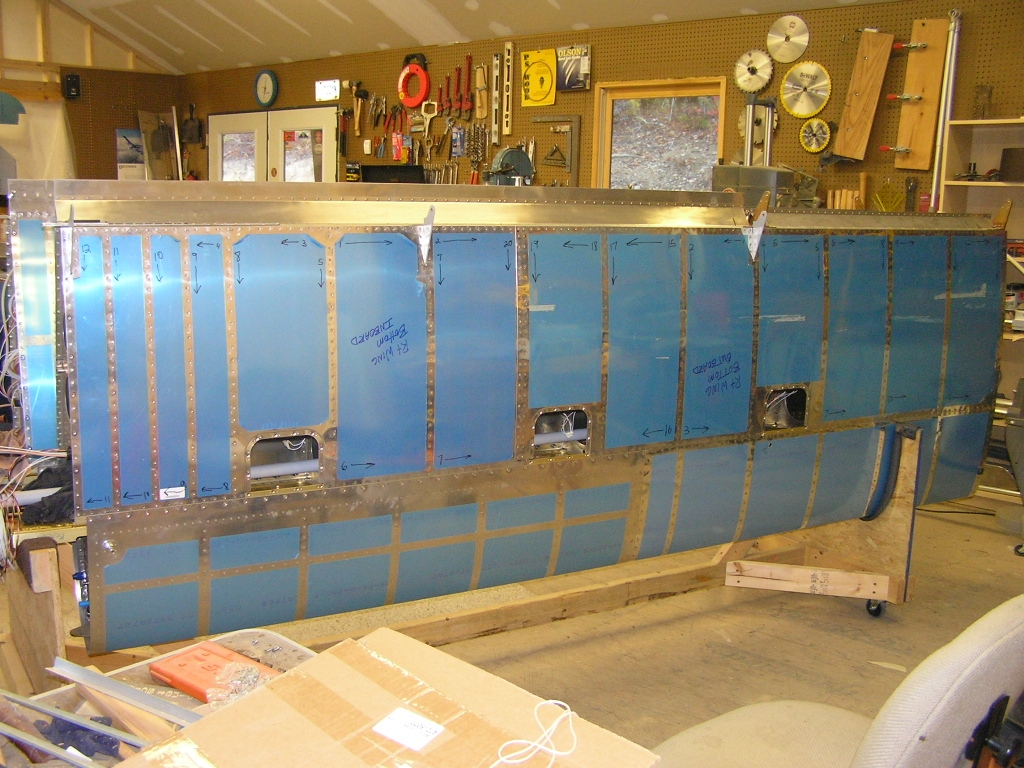
| Riveting Wing Bottom Skins | ||
| 10/13/07 | Before I can install and fit the wings to the
fuselage I need to finish riveting the bottom skins. I had
already installed the Gretz pitot mount but still need to finish
the plumbing and electrical runs. Since I have conduit
installed, I am good to go. I can install the wingtips
well after I fit the wings so that task will wait as well as
running the wires and antenna cable.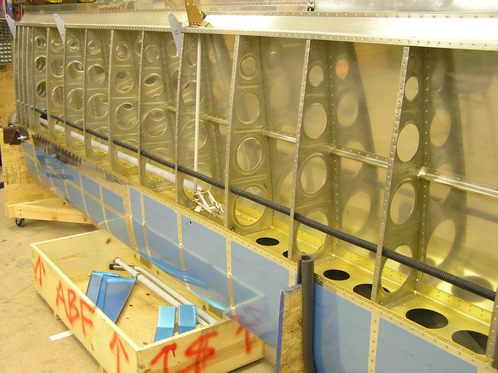
I also wanted to help secure the flex conduit in the ribs so I
applied a bead of clear RTV silicone at several ribs. I began by dimpling and
riveting platenuts on the inspection panel covers. |
2.0 |
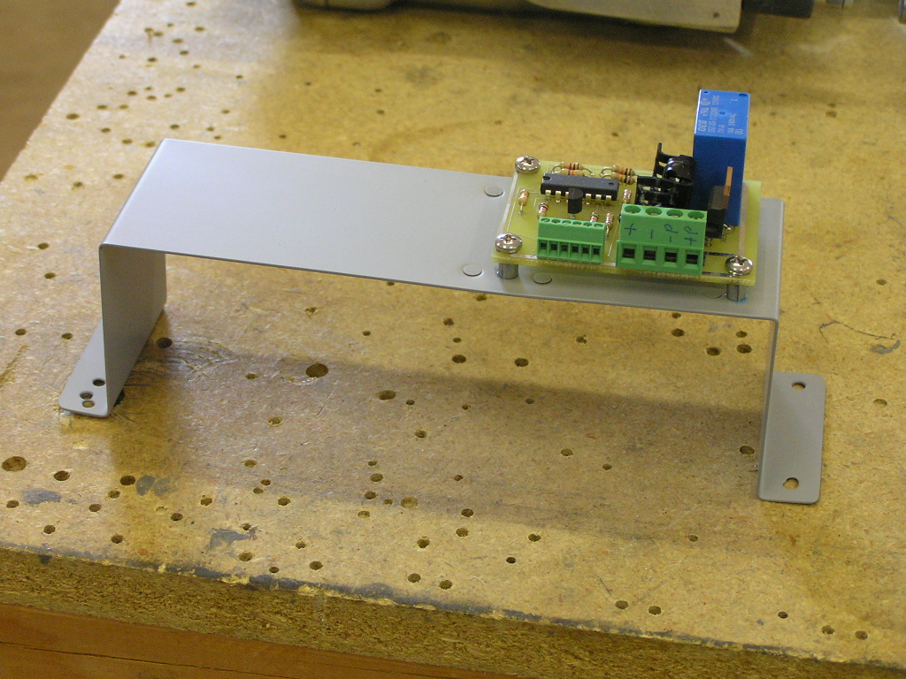
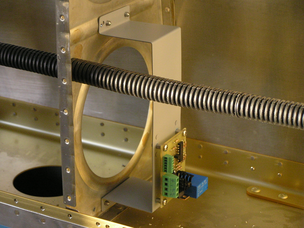
| 10/14/07 | Gretz Pitot
Install I had to grind the Gretz pitot in order for it
to fit inside the mount tube. I also had to fabricate a
bracket to mount the Gretz electronic control module. The
pitot is designed to work with the ECM but the wires from the
pitot are only about 18" long. The wires must connect to
the ECM as well as the power and ground. I need to install
the ECM one bay out from the pitot tube in order to have access
to it via an inspection hole. I
riveted the ECM bracket in the adjoining bay with the bellcrank.
I decided to apply a piece of heat shrink tubing over the wires
coming out of the pitot tube to help protect them when routed
through the rib and around the bellcrank. |
2.0 |
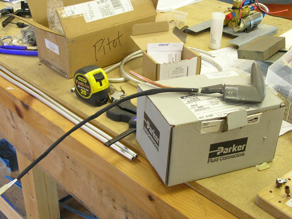
| 11/4/07 | I had to wait to install the pitot tube until I
had riveted the bottom skin on the left wing. I connected
the pitot tube to .250 OD plastic tubing with a piece of tubing
which was .250 ID. Finally, I safety wired the tubing
connection.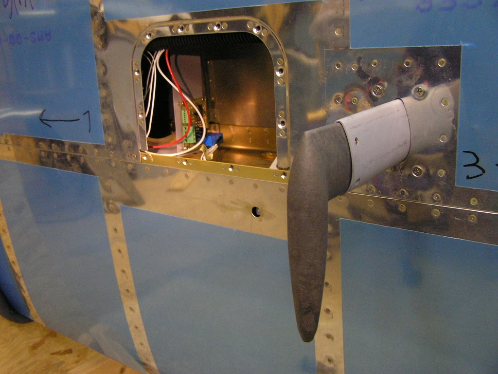 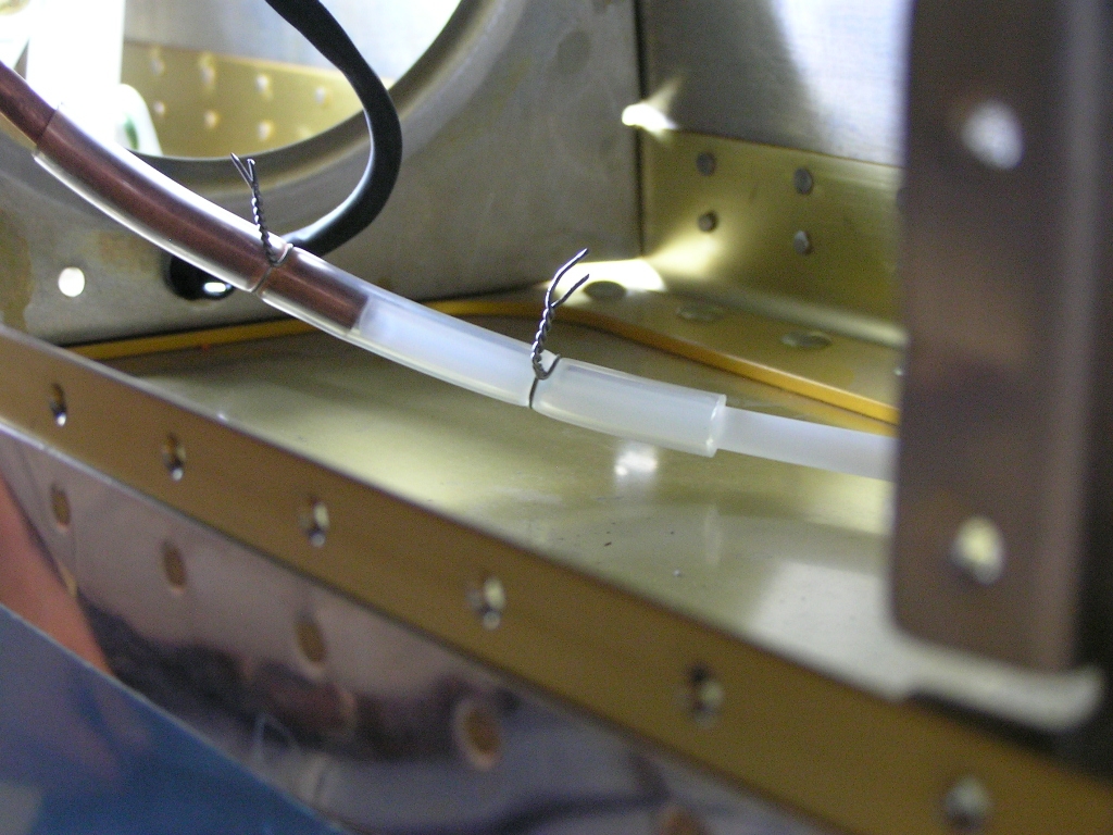 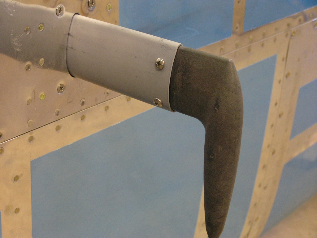 |
|
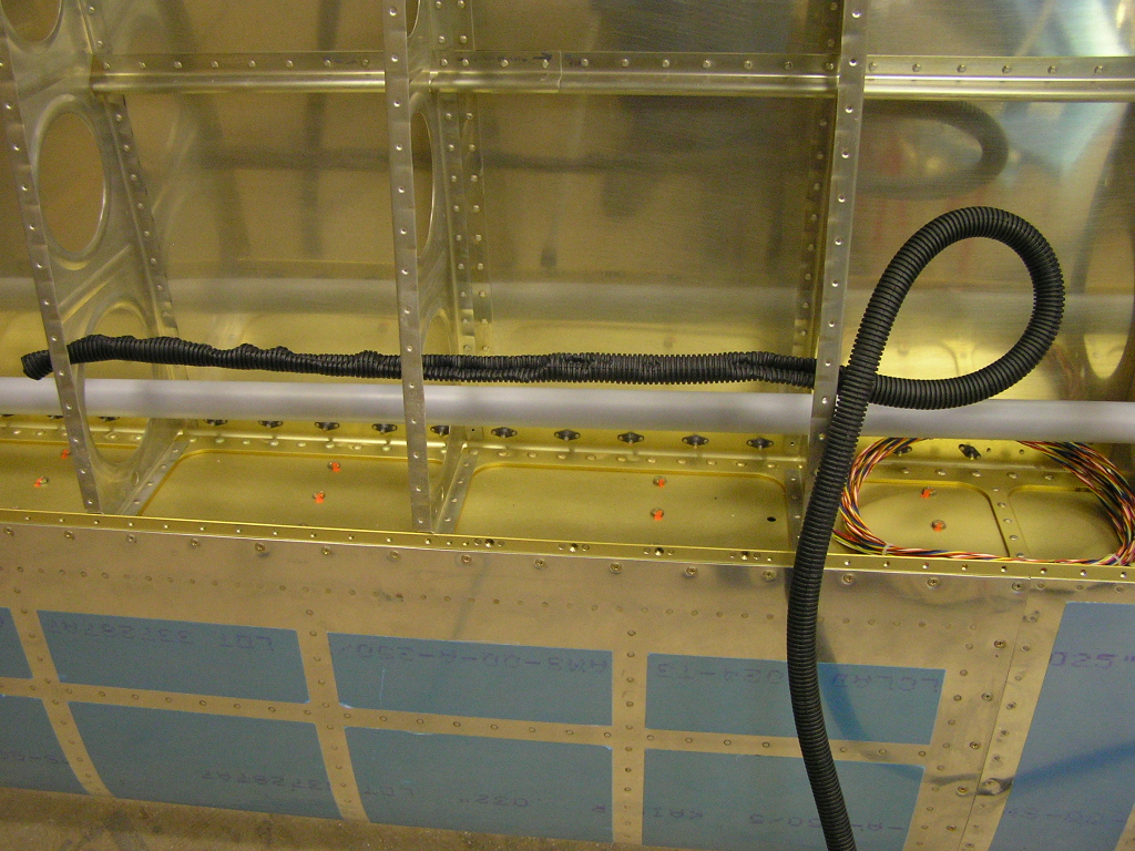
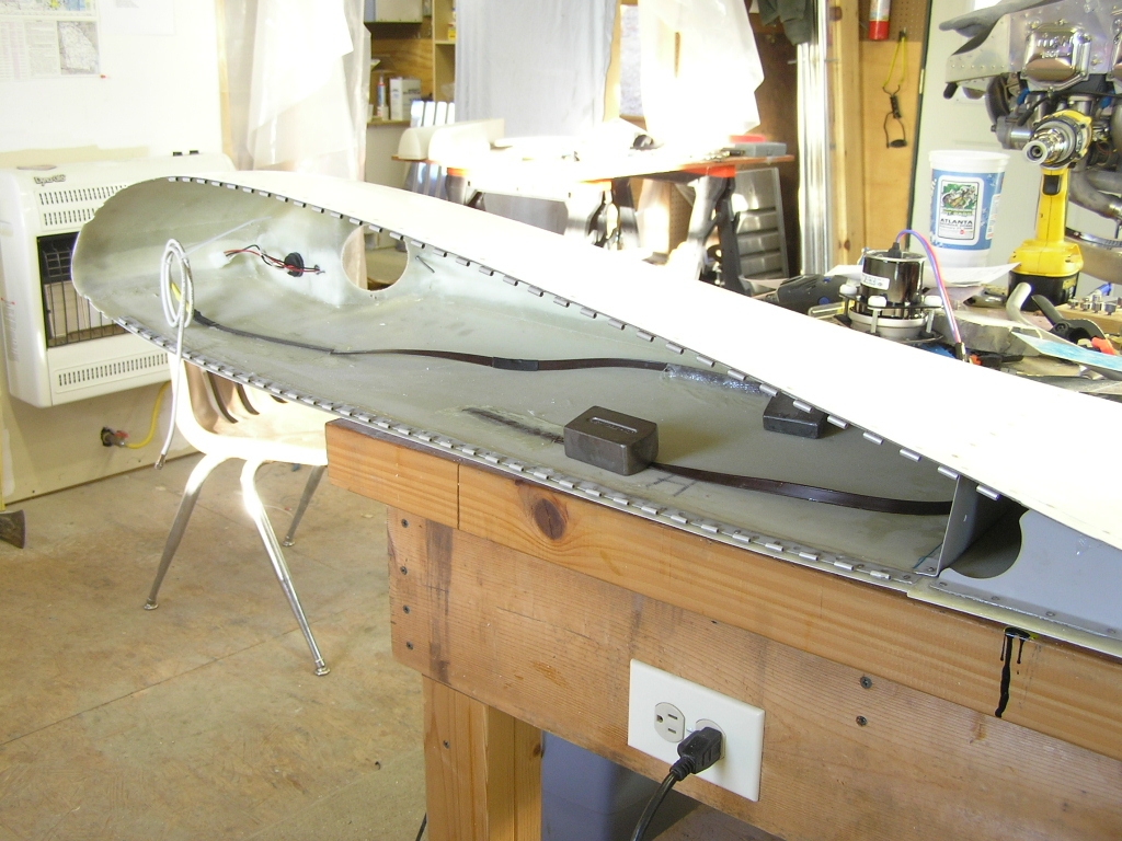
| 10/28/07 |
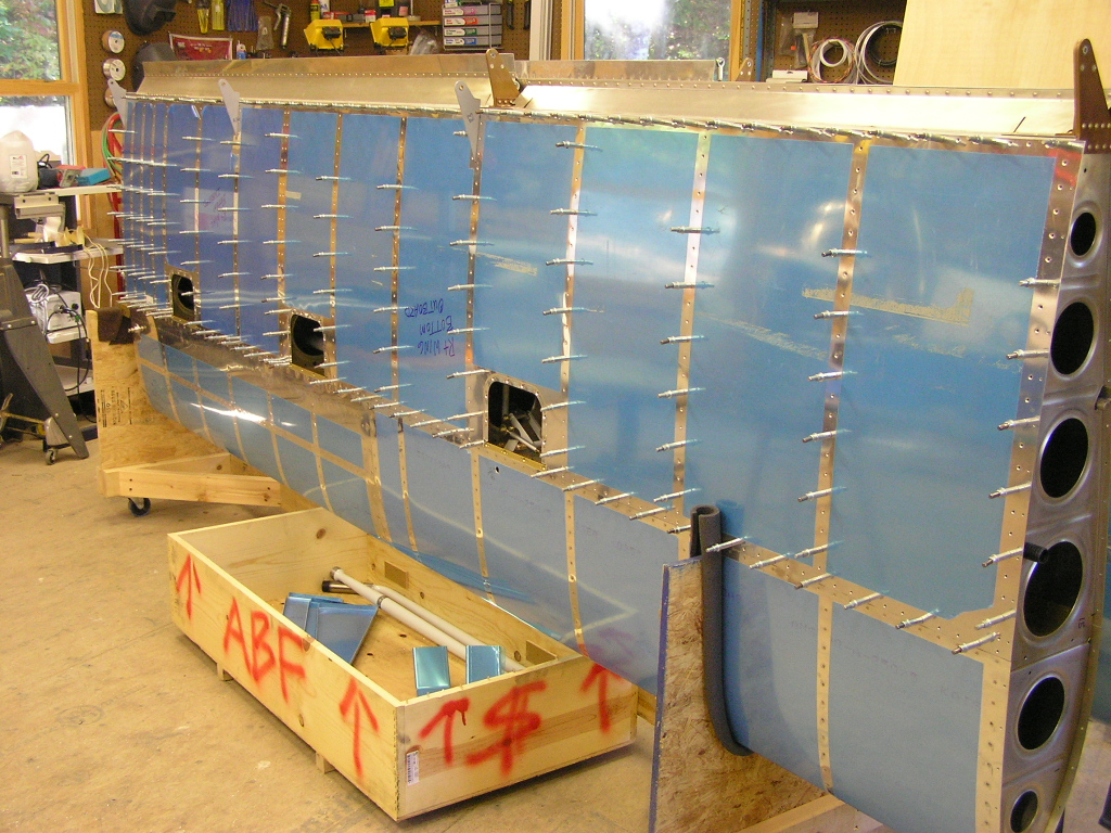
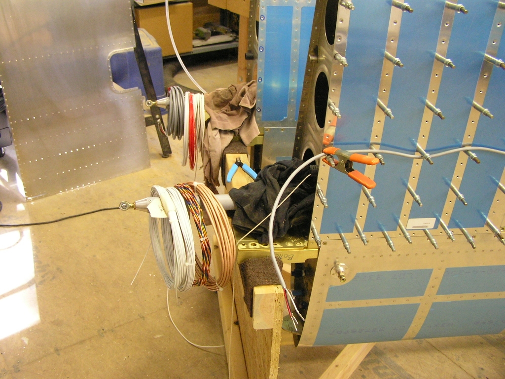
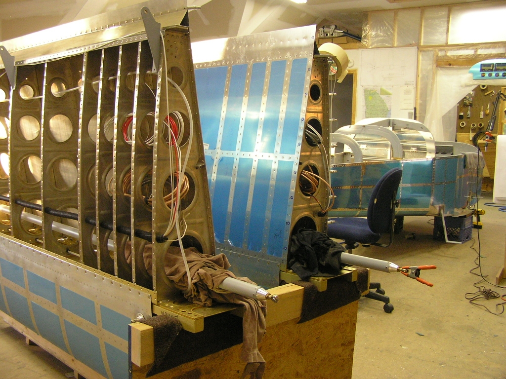
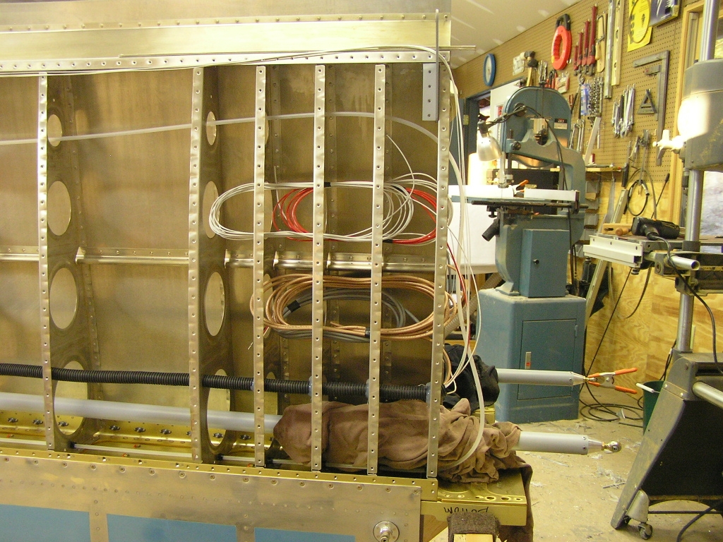
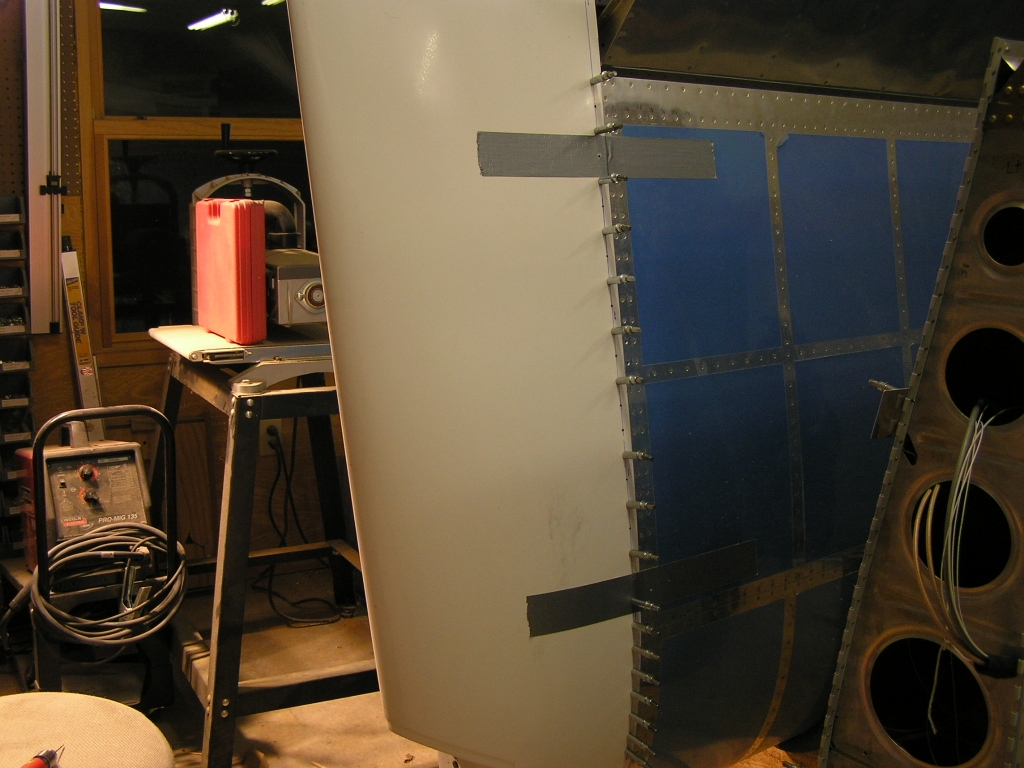
Wing Wiring I am trying to arrange a date for fellow builder (now flyer), Bill Repucci, to fly over from Charlotte, NC to guide me through fitting and drilling the wings to the fuselage. There is a possibility of him coming next weekend so I need to get busy. Before I can close up the bottom skins I need to pull the wiring and cables through the conduit. I am wanting to avoid any wing root wire connectors so I am
leaving 12 feet of wire "pigtails" for routing through the
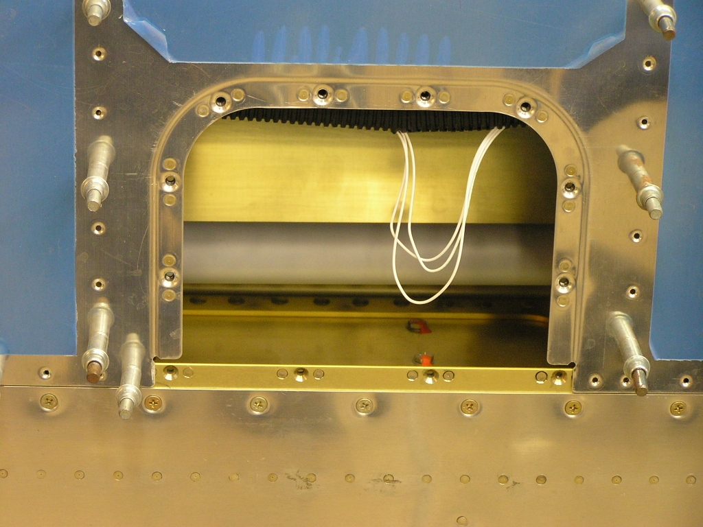
fuselage once the wings are permanently attached. I am adding LED lights at each inspection panel for light
when I pre-flight after dark. I will tie into a 22ga, +12v
wire where you see the loops. Here you can see how I have bundled the excess and stuffed it
in the lightening holes. |
4.0 |
| 11/2/07 | I received my order for additional RG-400 coax
from SteinAir for the Marker Beacon
antenna in the left wingtip and pulled it through the flexible
conduit. Next, I finished labeling the wires running
through the left wing. I printed labels and after cutting
them out, I covered with clear shrink tube and sealed with my
heat gun. |
1.0 |
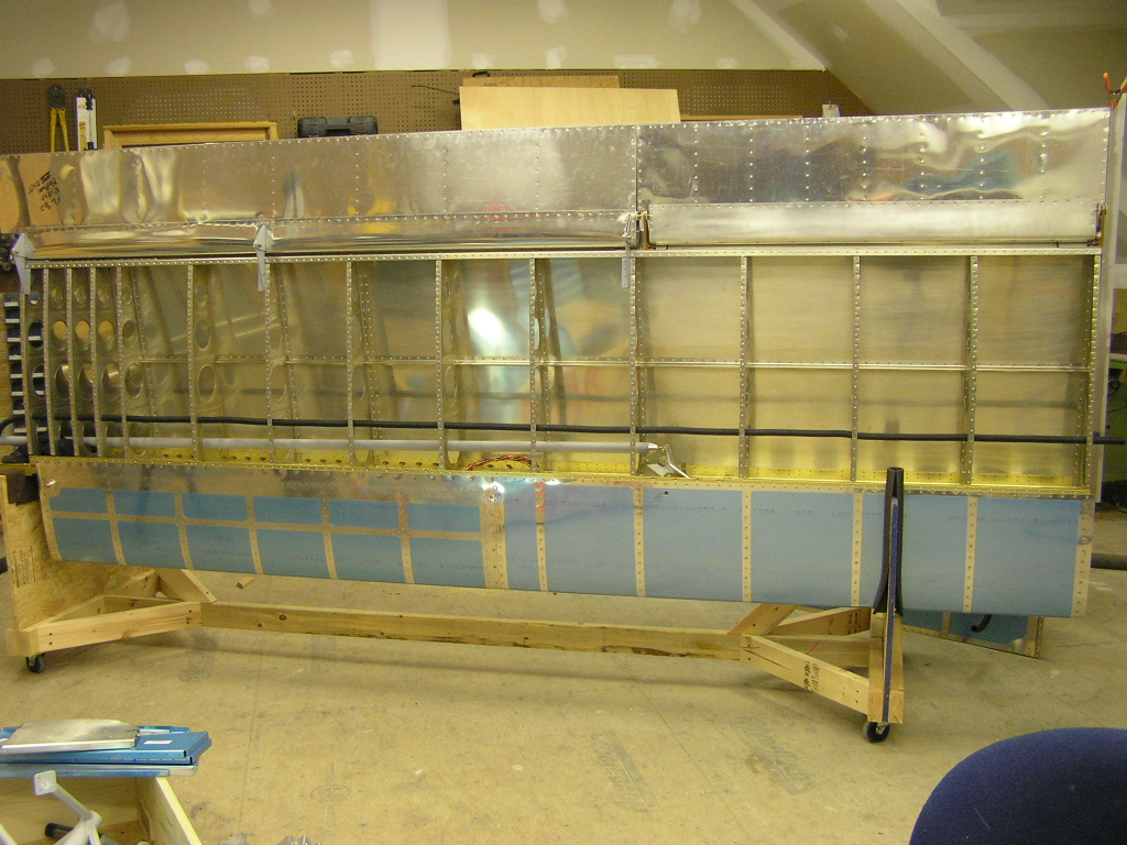
| 11/3/07 | While waiting for my riveting partner to arrive
I attended to several odd tasks. I had never riveted the
platenuts to the inspection panels on the left wing. I
also drilled a .250" hole in each inspection panel for
installing LED lights. 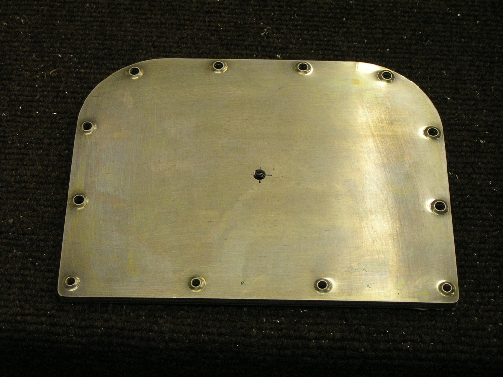 Riveting Bottom Wing Skins...Finally! Terry arrived late afternoon and we got busy riveting the bottom skin
on the right wing. I decided that since the wings are
already stable in their wing stands it made sense to rivet them
there. This is a task that will take much longer than you
realize. Four and a half hours later we finished.
One more wing to go... |
6.0 |
| 11/4/07 | Today Ben Bierbaum
came up to help me finish riveting the bottom skin on the left
wing. This was a tedious process due primarily to having
to work around the pitot installation.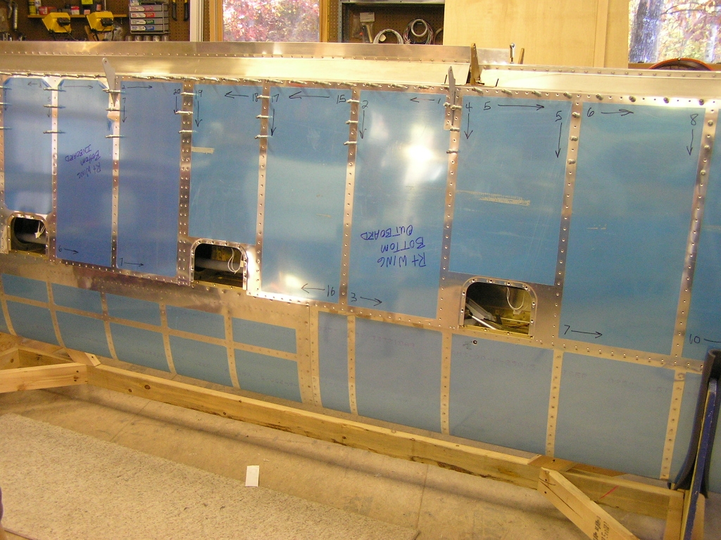 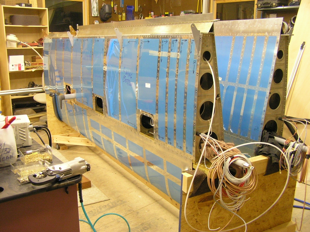
The only problem was when I dropped the bucking bar down into
the leading edge at the third outside bay... too far to reach.
Now I will need to figure out a way to get it out. |
8.0 |
|
HID Wingtip Light Install |
||
| 3/15/08 | If you have been following my search for
suitable HID lights in my R&D section
you would know that after several months of testing and
searching for the right configuration of lamps, bulbs and light
design I am pleased to say that I have found a light that meets
all of my design requirements. Thanks to the great guys at
HIDFoglight, Ed
and Aram, for their tireless searching and sending me samples to
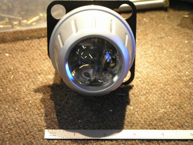
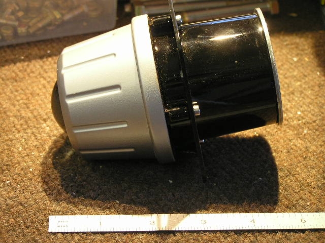
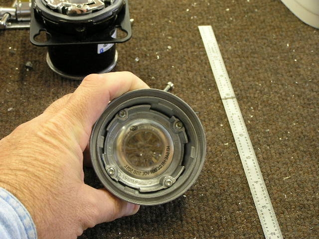
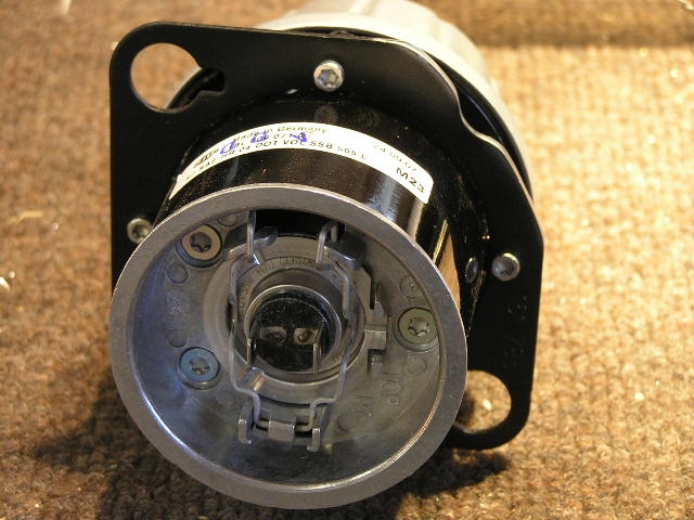
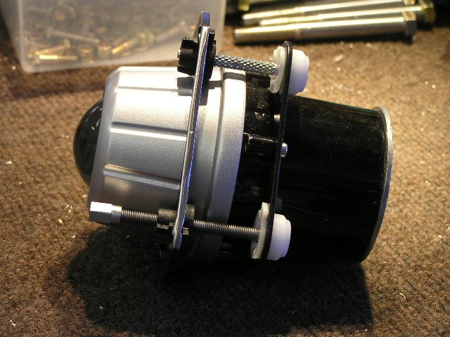
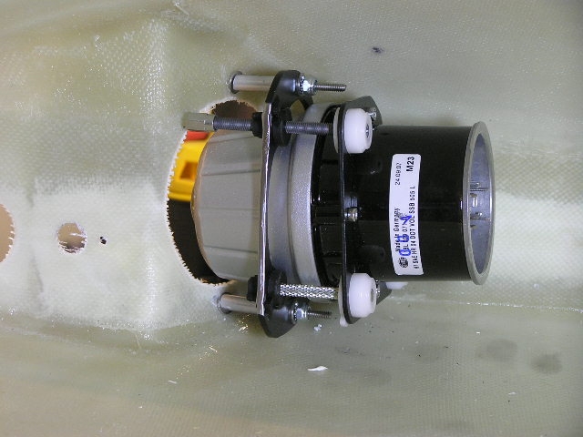
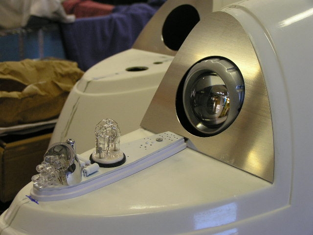
test. I installed the lamps in less than 6 hours from start to
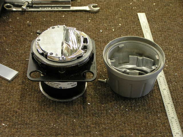
finish. The first step is to remove the lens section from
the lamp by unscrewing the gray shroud. Next,
remove the "half-moon" shaped plate.
The glass lens is sealed with an "O" ring and secured with four
screws.
One thing that shows the quality of these lamps is the foam
gasket where the lens attaches. The front of these lamps
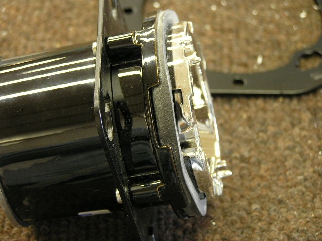
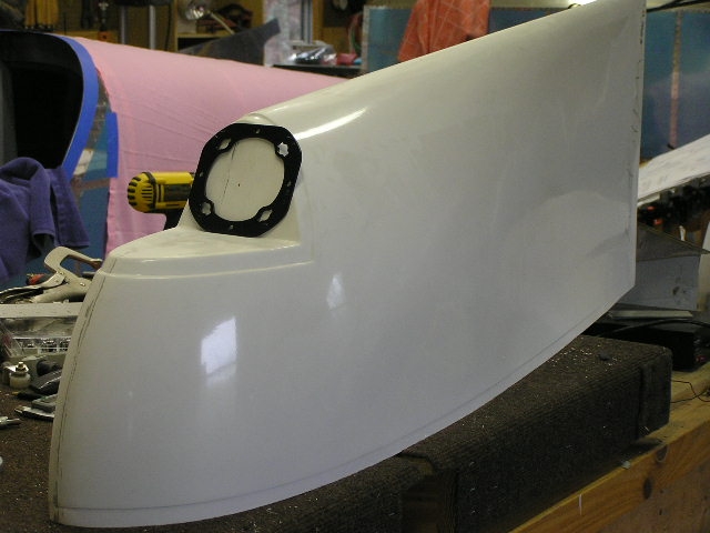
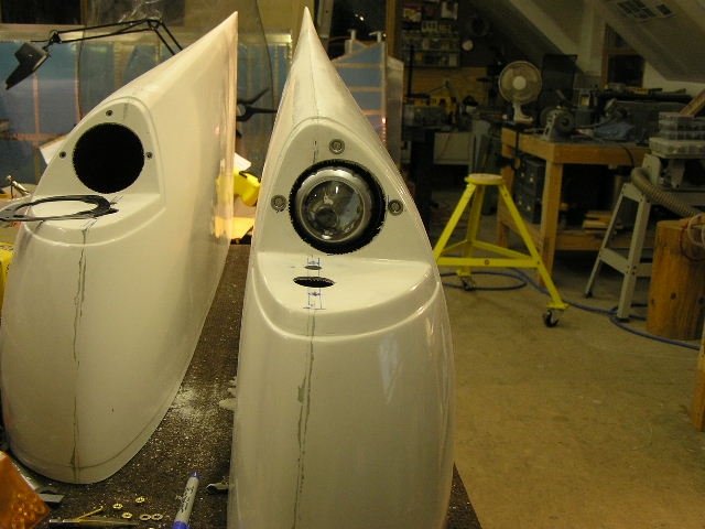
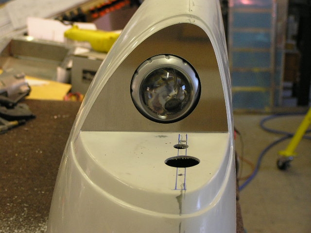
are water tight. You can now re-install the lens and set aside. Next you will
need to trim the attach plate for your wingtip style. My
installation is in an RV-9A which has a molded fiberglass
"notch" designed in the forward edge. As you can see, the
attach plate needs to be trimmed in order to fit inside the
wingtip.
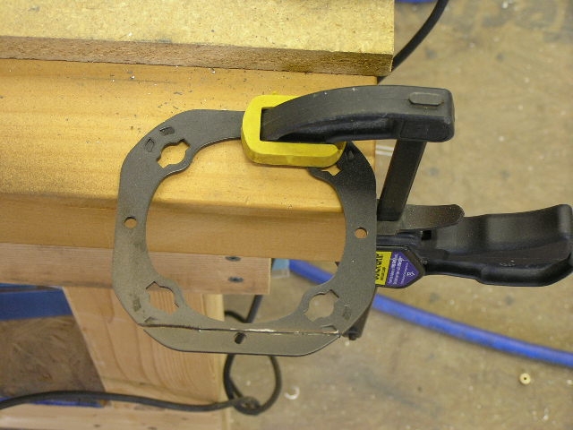
I placed the attach plate outside the wingtip and marked where
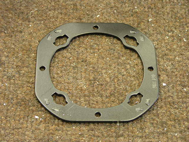
the trim cuts need to be made. I used a Dremel tool with
fiber cut-off discs to cut the thick steel attach plates.
I found that I could cut about halfway through the plate and
then bend and break off the cut section.
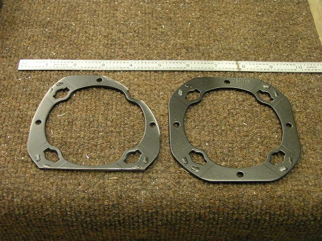
Each plate required three trimmed areas. Here you can see
the first attach plate after trimming and deburring as compared
to an original plate.
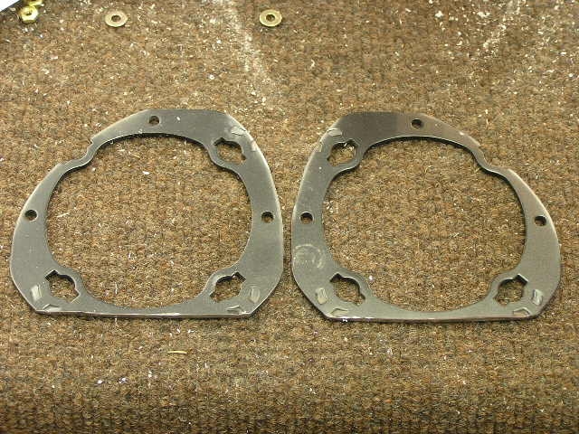
You can use the first trimmed plate as a template and mark the
second attach plate for trimming. (This is if you want to
install a second light in the opposite wingtip). When you
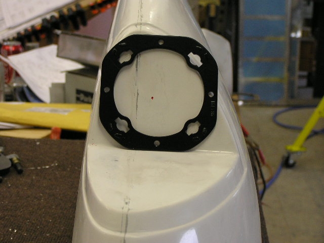
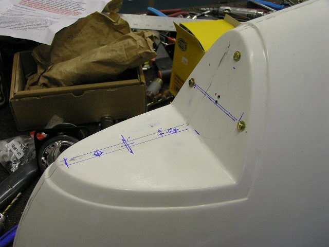
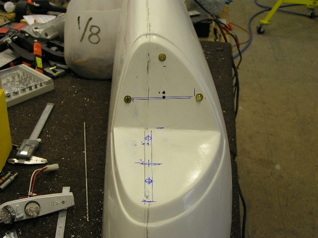
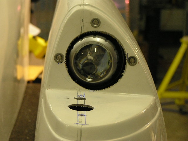
are done, the plates should look like this. Prepping the Wingtips
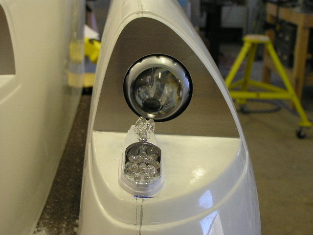
Next, I measured out where the attach plate screws would be
drilled as well as the 3" hole for the light in the wingtip.
Ignore the markings on the vertical section as these will be for
the nav/strobe lights.
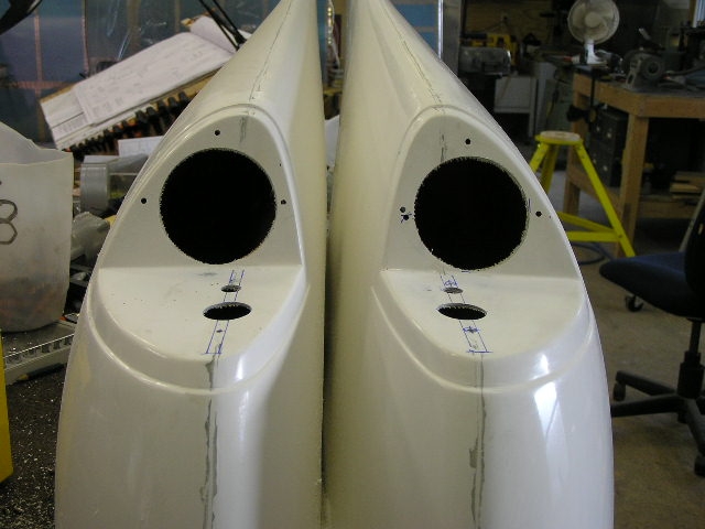
The hole for the lamp is cut at 3.0 inches using a 3.0" hole
saw. The HID lights generate quite a bit of heat so I
over-sized the cut in the fiberglass to allow adequate clearance
from the lamp. After the lights are installed I will be
attaching an aluminum dress plate which will have a 2.75"
diameter hole.
Next, I had to trim the lamp attach plate in order for the lamp
to clear the inside of the wingtip. The lamp attach plates
attach to the lamp with four screws. After removing the
plate I trimmed one edge and deburred and reattached to the
lamp.
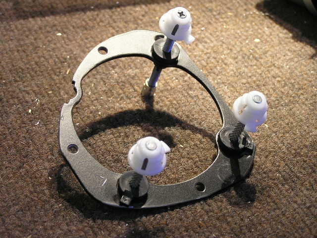
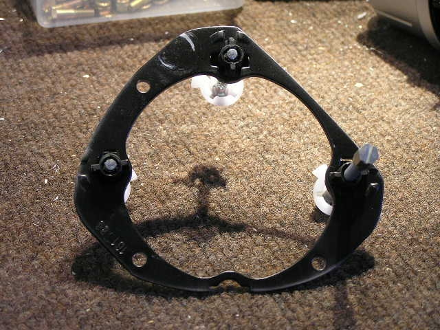
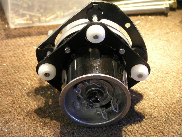
Next, install the three mounting lugs to the attach plate.
There are two "fixed" length lugs and one adjustable lug.
The lugs attach with "twist and lock" plastic nuts.
These lamps are designed to mount either in front of the attach
plate or behind it. I prefer to mount the lamps behind the
attach plate which places the entire lamp within the wingtip.
Next, you install the attach plate (with lugs) to the lamp
assembly. The white nuts fit through the holes in the Lamp
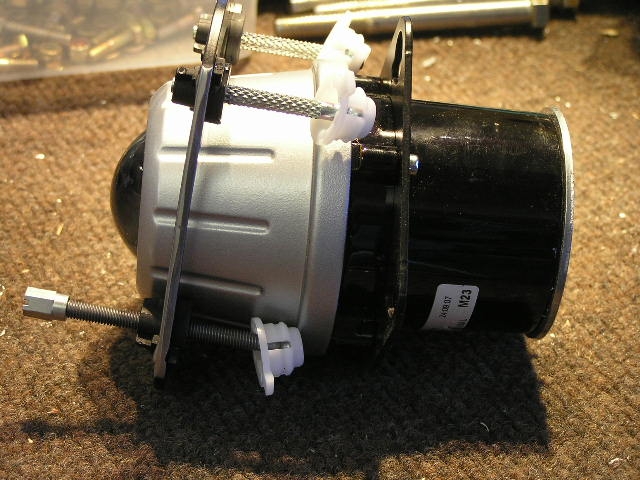
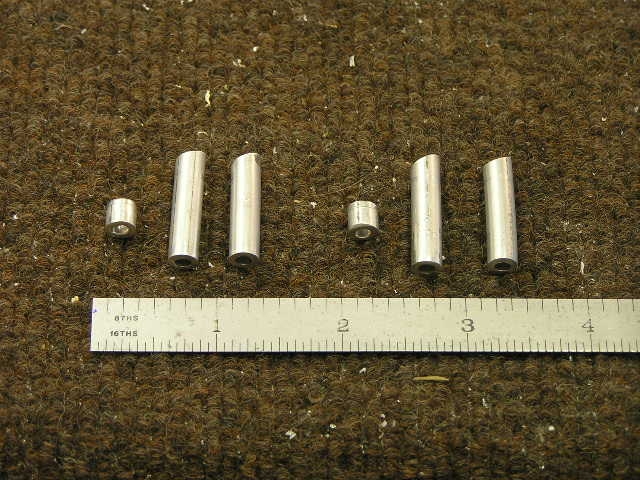
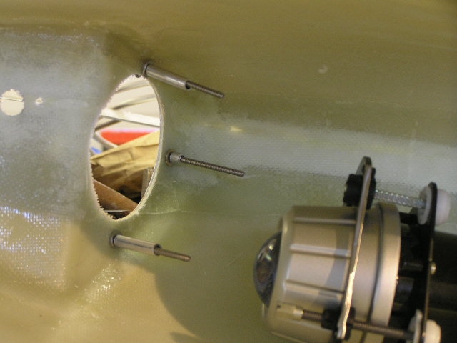
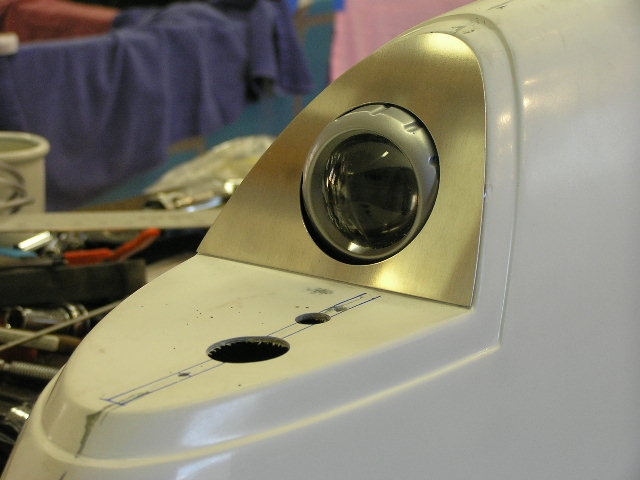
attach flange and the small white caps simply snap on the nuts. Installing the lamps In
order to achieve the proper stand-off from the wingtip I cut
three spacers from 1/4" aluminum tubing. Two of the
spacers are 1.0" and one is 0.25". I also ground a slight
bevel on one end of the spacers to match the angle of the
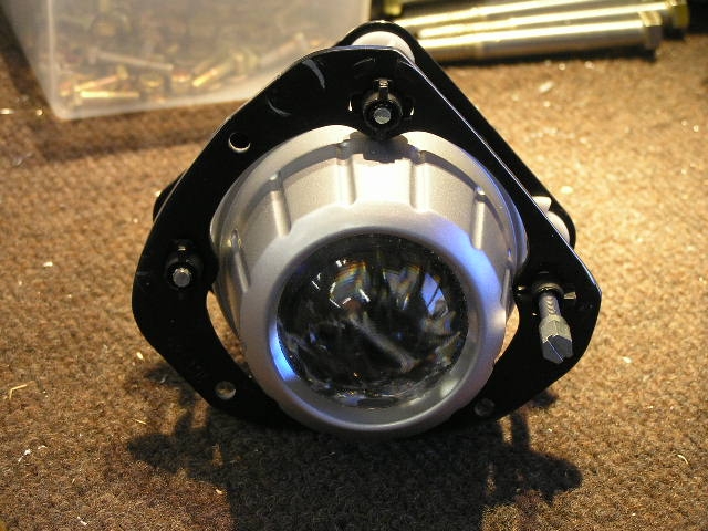
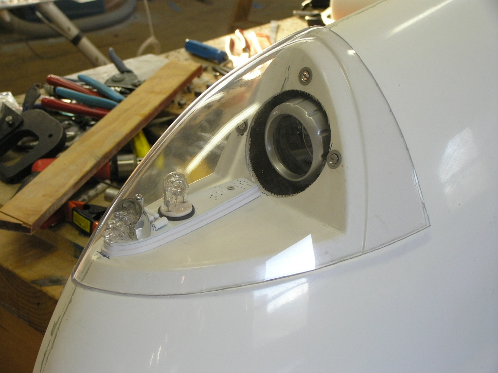
wingtip. To install the lamps I used the following parts:
Make sure to install the lamp so it is oriented "top up"
after the wingtip is installed on the wing. The lamps
have stamping to indicate the top side of the lamp. A
nice feature of these lamps is the adjustment screw which
allows you to "aim" the lamp for optimum light dispersion.
For example, you will want the landing light to aim directly
ahead while the taxi light would need to be aimed downward. Now, all that is left is to install the outer dress plate.
I will be attaching the 50-watt ballast to the outer wing
rib. HIDFoglight.com
will be offering these lamps to RV builders who wish to have
the finest in wingtip HID lighting. They will soon
also offer another HID lamp for those with the old Duckworks
halogen lamps. It will also be 50-watts and offer a
true retro-fit for the leading-edge lamps. (More info
on the leading-edge HID lamps will be available on their
website. Final pricing on the wingtip HID lights is
available on their website as well. If you would like
additional information on the installation of the wingtip
lights, please feel free to contact me
here. |
10.0 |
|
Wingtip Hinge Installation
|
||
| 1/18/09 |
I am following another tip from builder,
Mark Phillips, who came up with the idea of installing
the wingtips using hinges rather than screws. This allows
you to remove a wingtip in as little as one minute as opposed to
20 minutes removing screws. Also, you don't see those
nasty screws in the tips.  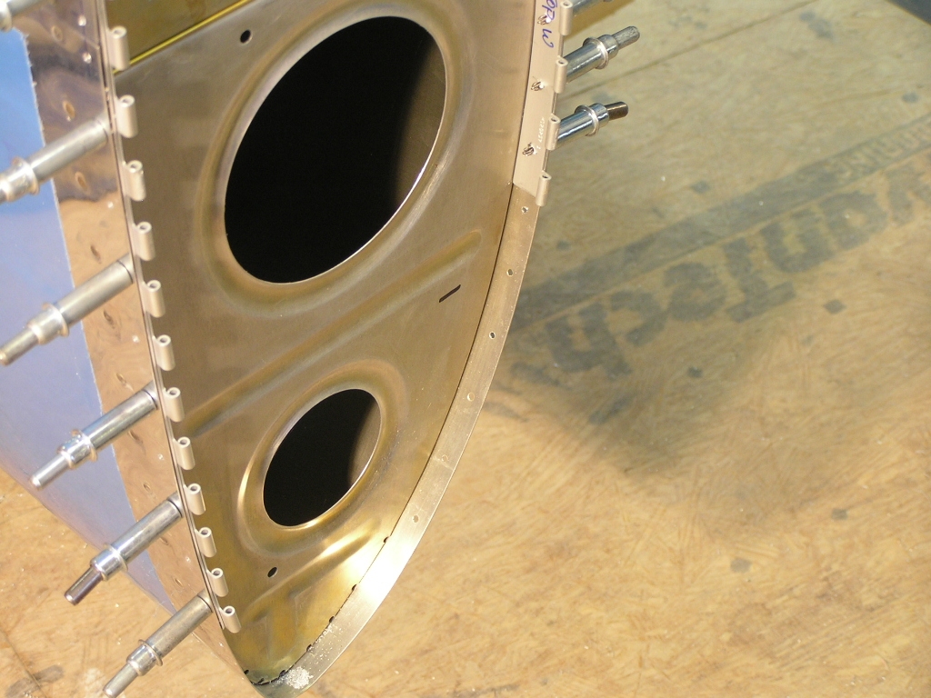 |
6.0 |
| 1/20/09 |
Tonight I finished drilling the hinges and spacers to the L & R
wing tips and deburred. I also countersunk the spacers for
the wing tip dimples. |
1.0 |
| 1/23/09 |
I fabbed some AL pieces which will be guides to hold the tip in
place as I later drill to the hinge. I then spent a lot of
time trimming the tip to ensure a good edge where the tip meets
the wing and to make it as clean as possible.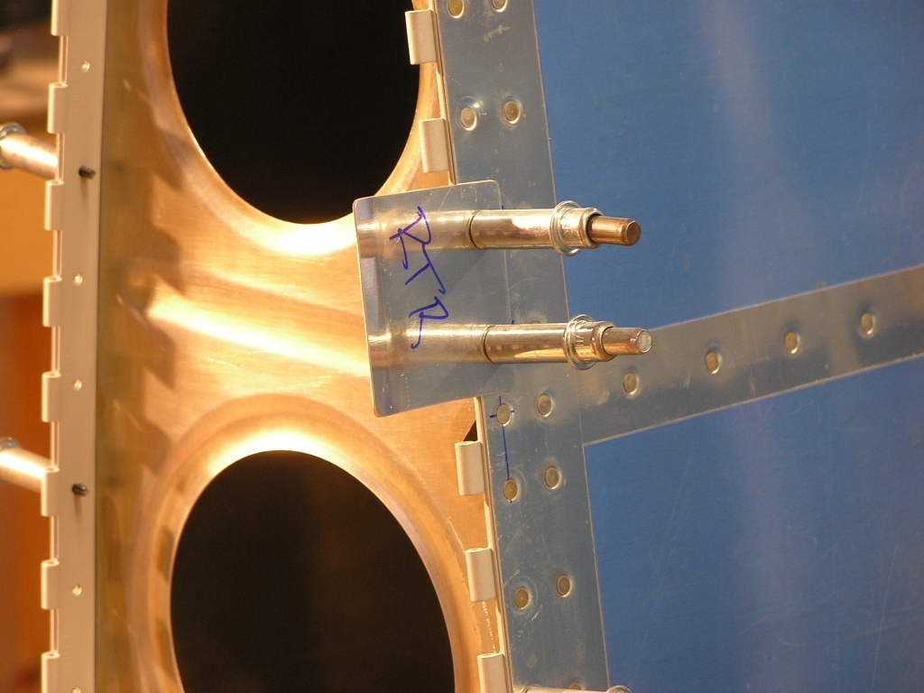 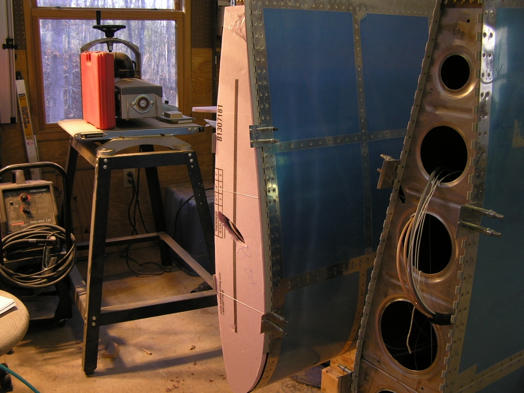 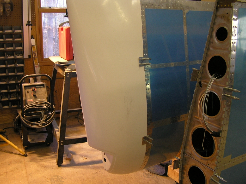
I then drilled the tip to the hinge using 1.25" rivet spacing. |
5.0 |
| 1/24/09 |
I repeated the steps for the right tip and epoxied and riveted
the left tip hinges. I ran out of
West System 206 hardener so I will epoxy the right tip
hinges in a few days. I also had to order some UHMW block
for the hinge pin retaining block.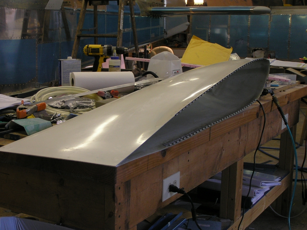 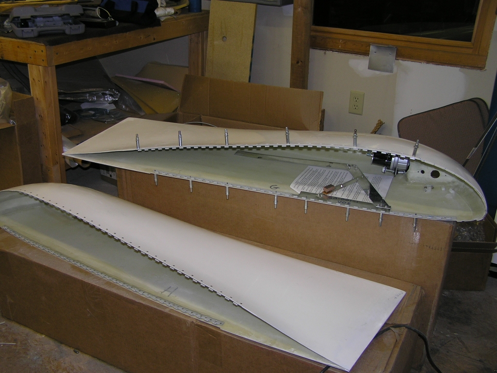 |
5.0 |
| 2/8/09 |
I bonded and riveted the right wingtip upper hinge. I
bonded the Archer Marker Beacon antenna in the left tip and
started bonding the APRS antenna in the right tip.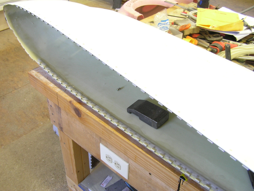 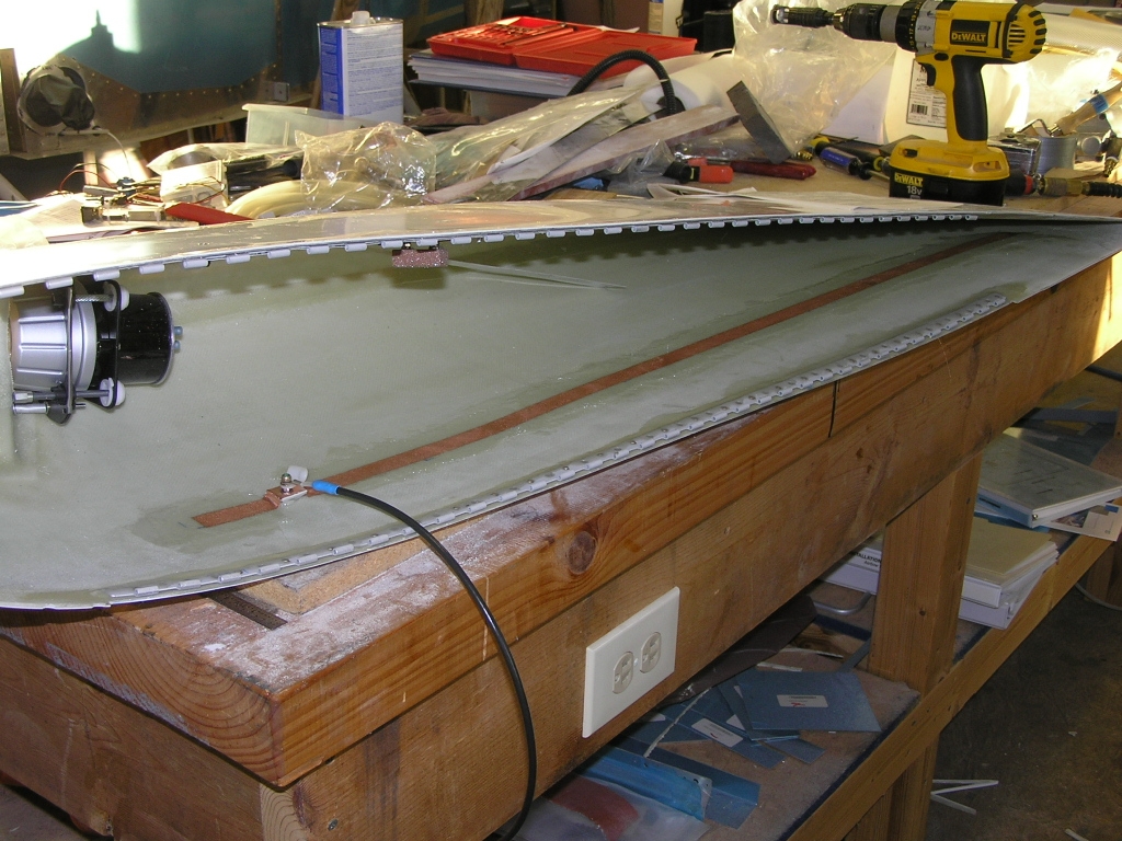 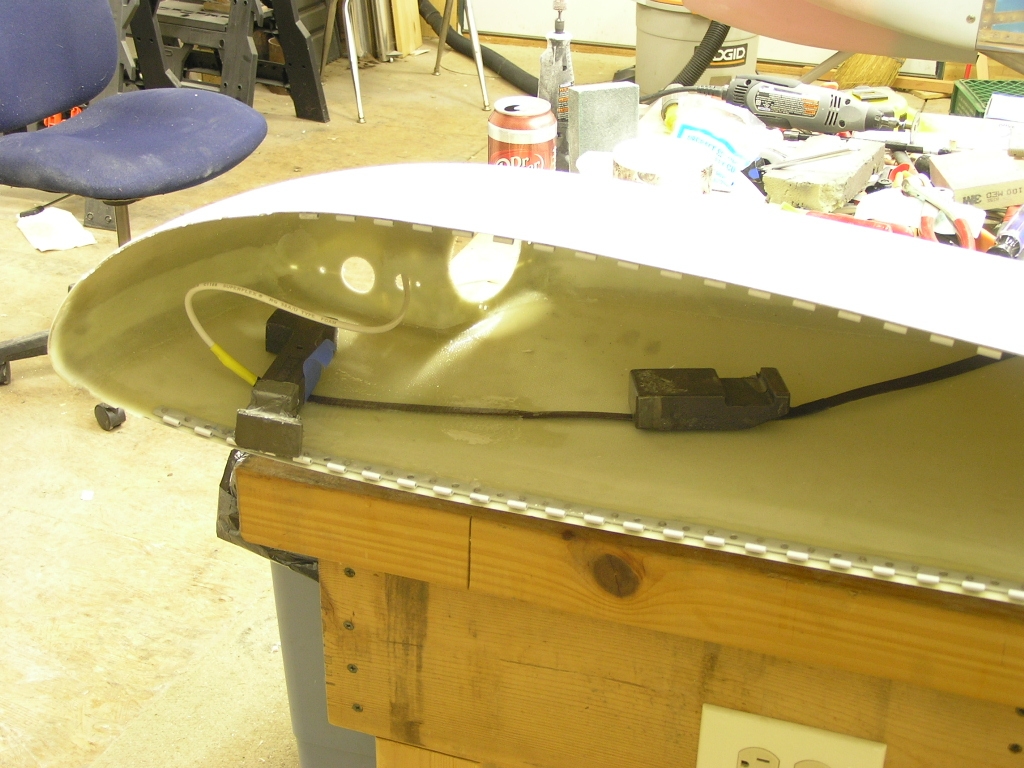 |
2.0 |
| 2/22/09 |
I have been working on the wing tips off and on between other
tasks but have been able to install the tip ribs. I had to
drill the flange in the lateral ribs and use a back light in
order to drill them to the tips. This worked great.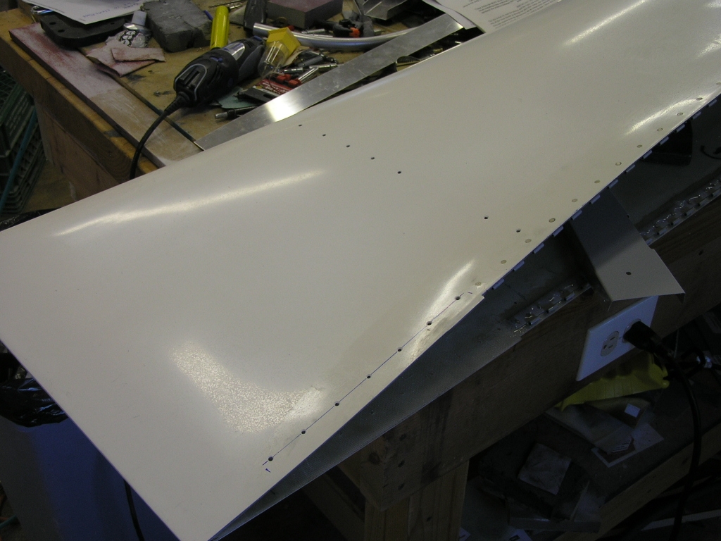 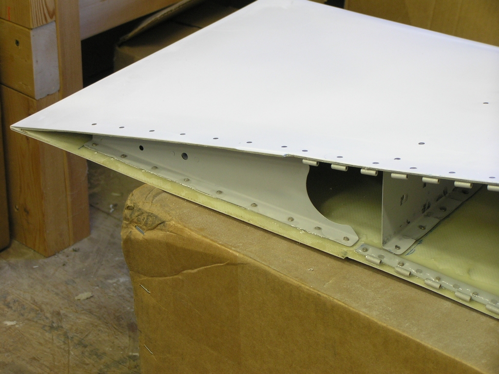 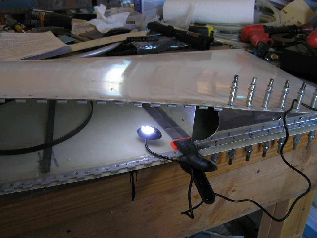 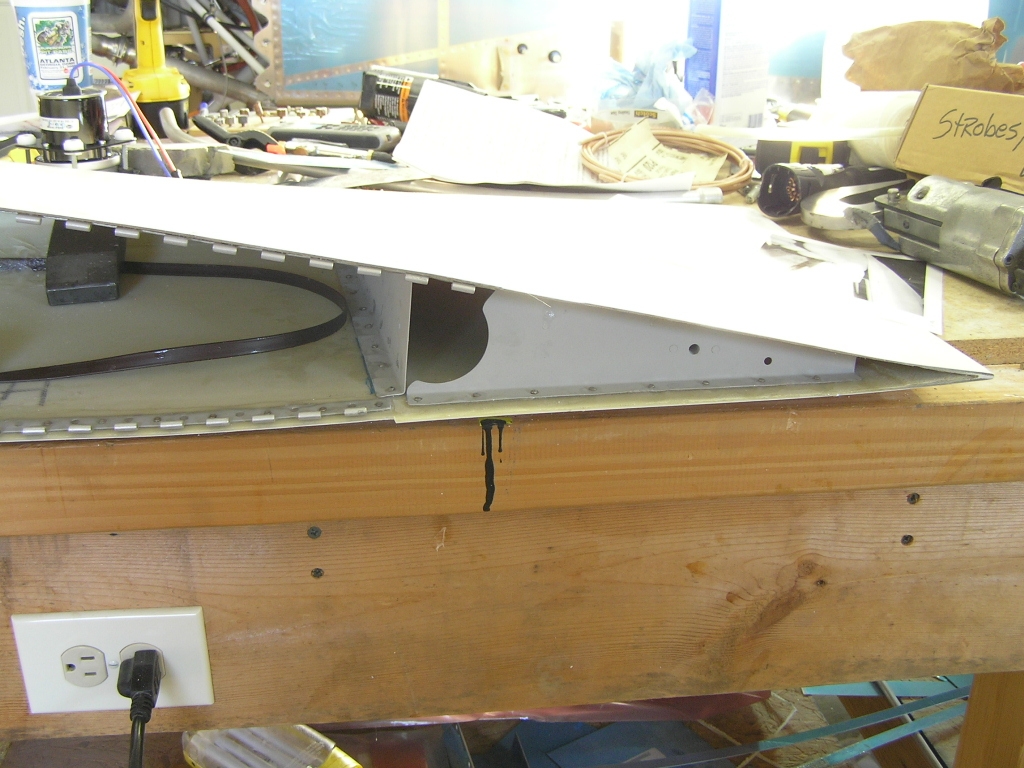
I also glassed in the APRS antenna in the right wing tip. I fabricated and drilled the hinge pin retainer blocks and
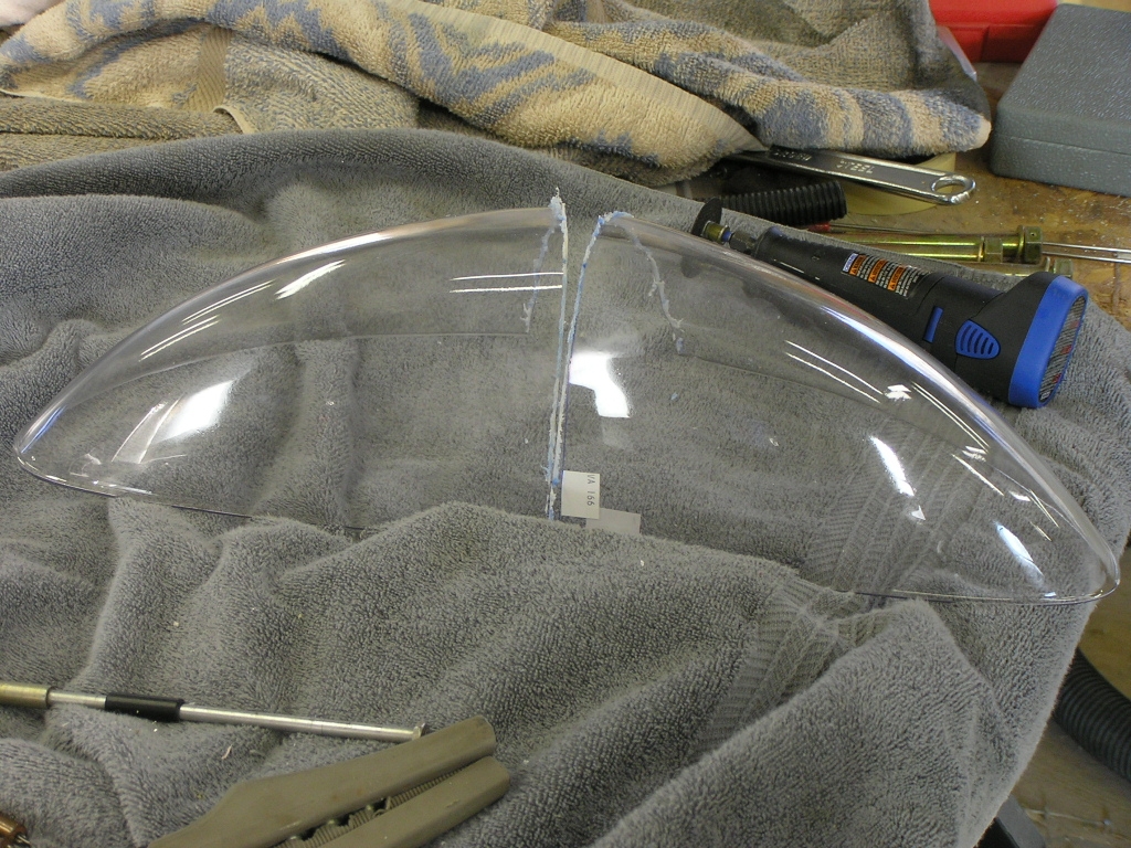
test installed them. I need to order some proper Molex connectors for the
navigation lights so I jumped ahead and started trimming the
lens covers using my Dremel tool with a cut-off wheel. |
4.0 |
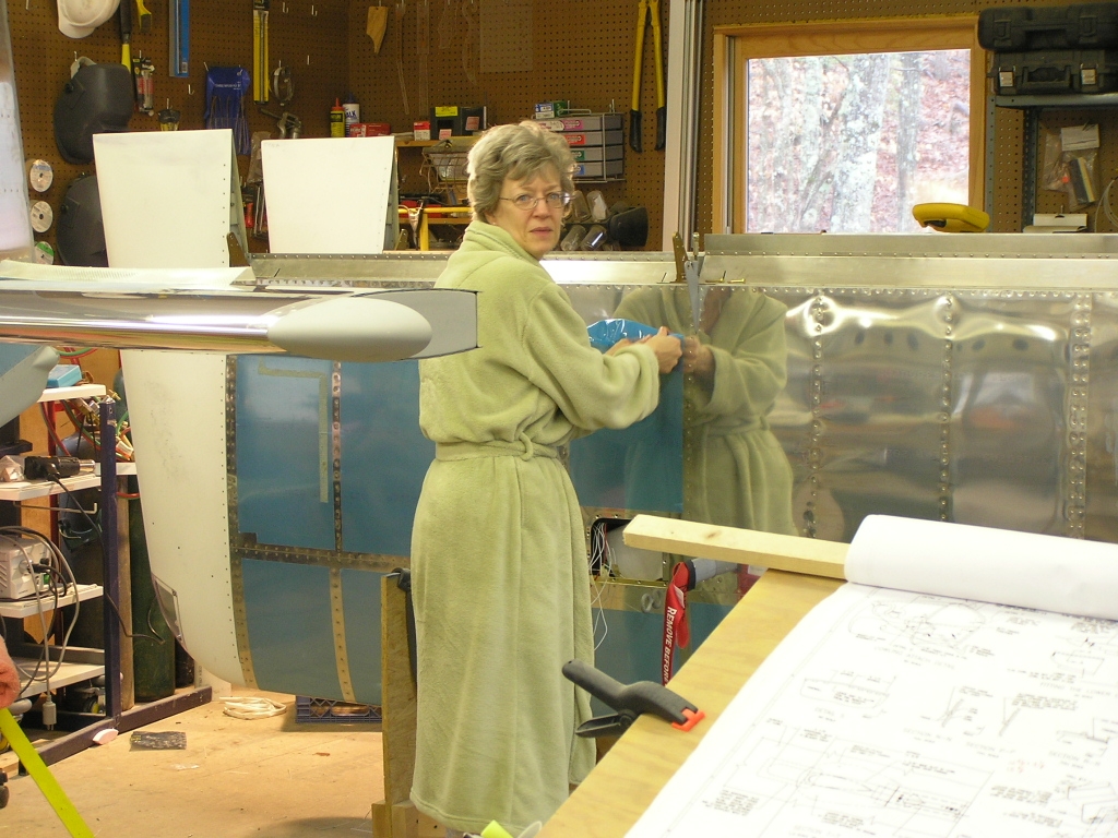
| 3/7/09 |
Finished the wingtips! I will be installing the light trim
covers once flight testing confirms the proper alignment.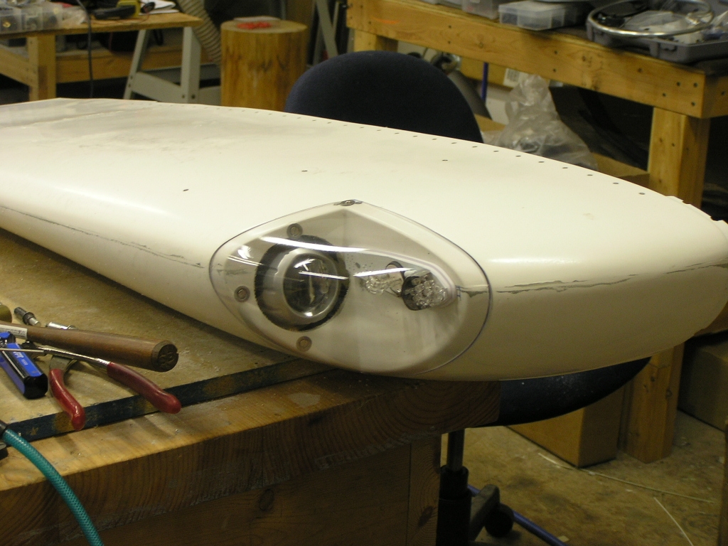 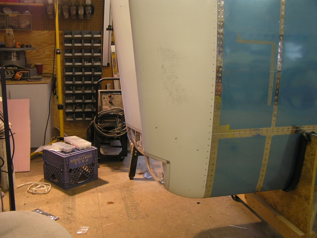
Here is Lynne stripping the plastic in her housecoat.... |
2.0 |
|
Total Hours this Page |
||
|
Total Hours Wings |
||
| Next: Fuselage |
Copyright ©2005-2009
Hosted by NTI Networks